Using the PCB in post #872 as an example. Unfortunately, my 60VDC PS lasted about 10 minutes so I'm back to 30VDC.
I was testing my CCS PCB shown in post #872. With the 159ZL as a load I was getting a consistent 3.3ADC and about .7VDC drop across R4 with 30 VDC supplied.
Regards,
Dan
I was testing my CCS PCB shown in post #872. With the 159ZL as a load I was getting a consistent 3.3ADC and about .7VDC drop across R4 with 30 VDC supplied.
Regards,
Dan
My Schade 50Watts monoblock is powered by two interconnected bench lab PSU's in total = 60V and 10A capability max.
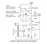
Input audio transformer bring clean sound and is give more immunity against external noise and perturbations.
About SMPS ....well maybe build huge DIY 60 V | 40 A BRICK
High power adjustable switching power supply (SMPS) 3-60V 40A
Edit : ready made from RS cost a small fortune :
SWS600L-60 | TDK-Lambda 600W Embedded Switch Mode Power Supply SMPS, 10A, 60V dc | TDK-Lambda
Have a nice sunday 🙂
Even though I'm building a linear supply I'm purchasing one of these for testing.
350W Switching Power Supply 60V 5.9A 115/230V for Stepper Motor CNC Router Kits: Amazon.ca: Electronics
Regards,
Dan
think about putting fuse in rail
There's fuses in the substation near my home! 😱
And on that note everything is a fuse. Even 14AWG wire has a limited ampacity before it opens? 😉

Hi RobLK,
That looks pretty good I gotta say. I personally don't intend to use one of the hockey puck Fets (I've some irfp150's here for a lower powered version).
I'm very happy to do the design work on a PCB for them though - does anyone have the eagle part for a hockey puck?
I'm working on the full blown kilowatt version in my spare time and doing PCBs. Since I have a couple hundred IRFP240s laying around I was wondering if I could produce a lower powered version with minimal changes to my original PCBs?
Regards,
Dan
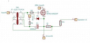
Question about the schematic in post 12.
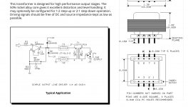
The Jensen transformer's physical polarity, is it flipped manually to match the schematic or does the polarity markers end up being marked the same as the schematic?
I know it's stupid question, but I'm afraid to wire it incorrectly.
I guess I can place the secondary in series and just flip the connection to the circuit board or next connection points. 😱
Sorry, I have a little mental block with this for some reason. 😱
After reading Soundhappy's post here's with what I came up with.
Regards,
Dan
Attachments
Yes, Dan OK 🙂
Jensen pins numbers with the dots are 1 and 2 for primary and 5 and 6 for secondary.
In case Your preamplifier has low output impedance = 25 Ohm´s or less , jfet´s buffer at the Schade50 signal input are not necessary,
but if use others preamplifiers with higher impedances then buffer are the great solution.
Wider audio bandwidth guarantees
Attachments
Yes, Dan OK 🙂
Jensen pins numbers with the dots are 1 and 2 for primary and 5 and 6 for secondary.
In case Your preamplifier has low output impedance = 25 Ohm´s or less , jfet´s buffer at the Schade50 signal input are not necessary,
but if use others preamplifiers with higher impedances then buffer are the great solution.
Wider audio bandwidth guarantees
Sound happy,
I’m in the midst of making a PCB and because it’s used in Papa’s CSX1 VFET I’m going to include a buffer as an option. That way if it’s needed it’s only a case of soldering in a few components. Of course, I’m talking about the one in post #595.
Regards,
Dan
Sound happy,
I’m in the midst of making a PCB and because it’s used in Papa’s CSX1 VFET I’m going to include a buffer as an option. That way if it’s needed it’s only a case of soldering in a few components. Of course, I’m talking about the one in post #595.
Regards,
Dan
CSX1 Vfet buffer are very simple and without capacitors.
Need regulated (+) and (-) 12V psu . This increase the total number of components. I use small separate 15 V transformers.
This was the reason why my 3 boards set for mono channel are :
1| CCS
2 |IXYS audio signal
3| bias psu for IXYS with buffer psu circuit and jfet's impedance buffer path.
Finally is a bit more complex amplifier to build. 😀
Do You make 2 boards version with all of this included ?
Kind regards
CCS learning curve. My CCS seems to work fine. With 1,2, and 4 ohm loads it produces close to 3.5 ADC even though it drags my power supply down to 50V. I suspect I might be in line with others in changing the value of of the 10K resistor as outlined in post #49.
Regards,
Dan
Regards,
Dan
My CCS seems to work fine.
How many volts at the IXFN drain 28 ?
I stay at non more 3.2A current because is made heatsink very hot after 2 hours 🙂
Attachments
I was also getting 3.5A. I changed the 10k to 16k and the current went down to between 3.2 and 3.3A.
CSX1 Vfet buffer are very simple and without capacitors.
Need regulated (+) and (-) 12V psu . This increase the total number of components. I use small separate 15 V transformers.
This was the reason why my 3 boards set for mono channel are :
1| CCS
2 |IXYS audio signal
3| bias psu for IXYS with buffer psu circuit and jfet's impedance buffer path.
Finally is a bit more complex amplifier to build. 😀
Do You make 2 boards version with all of this included ?
Kind regards
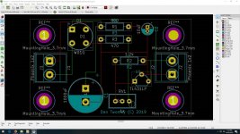
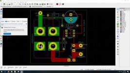
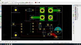
This is my first shot at making PCBs so there may be more revisions yet. I've built a standalone bias board as seen below. Also seen below is the latest revisions of my CSS and input boards. I'm a bit perplexed over a buffer PSU circuit. I don't want a ultra high-end Salas regulator, but I don't want to stick in any old LM317.
Regards,
Dan
Attachments
How many volts at the IXFN drain 28 ?
I stay at non more 3.2A current because is made heatsink very hot after 2 hours 🙂
Can't really measure that voltage because I'm just loading the CCS with a 1 ohm resistor. The bottom half of the circuit isn't connected. I'm making two boards because I'm planning to have each IXFN on it's own volkswagen sized heatsink. Thus two boards. What may have just dawned on me is that only the CCS IXFN will produce any real heat? The bottom amplifier IXFN will not? If this is the case I could easily put everything on one board for a far better solution?
Regards,
Dan


What may have just dawned on me is that only the CCS IXFN will produce any real heat? The bottom amplifier IXFN will not? If this is the case I could easily put everything on one board for a far better solution?
Regards,
Dan
Both will dissipate approximately the same amount of heat. The current is identical and the voltage drop across each is intended to be equal or close to equal.
This is my first shot at making PCBs so there may be more revisions yet..Also seen below is the latest revisions of my CSS ..
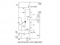
This CCS connection points C and D from 2SK77B Vfet version give two different audio signatures.
C have more H2 and slightly higher distortion = emulate triode sound
D bring H3 and less distortion = more up front and bright sound.
Both are perfect for two different preamplifiers or speakers.
I connected two positions switch between CCS points C and D and is opened a twice audio enjoyement from only one amplifier
 🙂
🙂  Best regards
Attachments
Can't really measure that voltage because I'm just loading the CCS with a 1 ohm resistor. The bottom half of the circuit isn't connected. I'm making two boards because I'm planning to have each IXFN on it's own volkswagen sized heatsink. Thus two boards. What may have just dawned on me is that only the CCS IXFN will produce any real heat? The bottom amplifier IXFN will not? If this is the case I could easily put everything on one board for a far better solution?
Regards,
Dan
I have a monster 12"(31CM)T x 18"(46cm)W x 3"(8cm)D heatsinks for each channel. I suppose I could get good thermal separation by mounting each IXFN a few inches apart.
Regards,
Dan
- Home
- Amplifiers
- Pass Labs
- 50w Single-Ended BAF2015 Schade Enabled