Pass DIY Addict
Joined 2000
Paid Member
So, now that the damage is corrected, I am back to looking for more power from my modified Aleph-X amp.
With 9610's and ~22v rails and ~9A bias, I get: ~85w/8R and ~130w/4R (33% efficient while drawing ~390w from the wall)
With JFETs and ~22v rails and ~9A bias, I get: ~80w/8R and ~ 100w/4R (25% efficient while drawing ~390w from the wall)
With JFETs with 10R source resistors, ~22v rails and ~9A bias, I get: ~70w/8R and 80w/4R (18% efficient while drawing ~390w from the wall)
The 9610 in the CSS measures Vgs=3.39v, gate to +PSU = 9.8v, and source to +PSU = 5.83v. I measure 4.72v across R23 and 4.73v across R25. I also measured the adjusted value of VR2 after re-biasing the amp at 157ohms, so I no longer need the 1K pot that I had substituted for the 200R pot.
What would be the impact if I changed R23/25 for a little more bias into the differential pair? My set of four JFETs are matched at 10.04mA.
Pass DIY Addict
Joined 2000
Paid Member
Thanks, Zen. This is what I wanted to do and how I was planning to approach it - I just wanted to make sure that doing so wouldn't cause a problem for the JFets. In the example you've provided, each JFET will be operating right at its Idss limit.
I'll give this a try within the next day or two and see how things change.
I'll give this a try within the next day or two and see how things change.
Pass DIY Addict
Joined 2000
Paid Member
Update to front end
Still using Graeme's schematic as a reference:
Rebiasing the input differential took some fiddling around to make it work. I decreased the jFet source resistors from 10R to 2R2. As I decreased the values of R23/25 in order to increase the differential bias, I needed to make other changes to compensate as well.
R23/R25 are now 270R - Vdrop across them = 4.76v, so about 17mA bias for the 2SJ74 pair on each side of the differential, so about 8.5mA bias to each jFet (was 6mA before changing R23/25). Relative DC offset remained at 0V, but I had to change R46/47 (McMillan resistors) from 10k down to 2k7 as abs DC offset was 17v and didn't come down over time. I was unable to adjust VR2 to bring absolute offset down at all, so I put a jumper across R56 and then readjust VR2. This allowed me to get 0V absolute DC offset.
Using a 1kHz sine wave, I can get 90w/4R and 78w/8R before the sine waves show obvious distortion on the scope with 9A bias and 22v power rails.
Rel DC offset now floats in the range of ~ +/-20mV.
With my wiring configuration, the jFet front end is more susceptible to noise and creates more hum at the speaker (1.0mV AC) than the 9610 input (0.2mV AC). Changing from an all-in-one bridge rectifier to Fairchild Stealth Diodes reduces speaker hum to the point where I almost can't hear it with my ear at the tweeter. Though, discrete diodes reduces rail voltage by another 1.5V. It seems that everything I try reduces power output...
The best configuration for power ouput into 4R loads seems to be:
9A output bias, 680pF for C9/C10, 5k1 for McMillan resistors, and 330R for R23/25 (14mA bias per side of the jFet differential). This provided about 110w into 4R, though only about 70w into 8R.
Last edited:
Hi Eric,
normally if Idss = 10mA you should bias the fets at around 5-6mA each to have the maximum voltage swing. Have a look at the Borbely articles again......
This will give you a total of 20mA just like a pair of 9610´s
5k1 for the McMillans is quite low and normally not very good for sound quality.
cheers,
William
Hi Guys,
Sorry for barging in after all this time. A while back I inadvertently hooked up 3-8ohm speakers per side to my Aleph-x and after a while the amp started distorting so I shut it down and unhooked everything and set it aside until I would have time to look it over. Well, today is that day. I pulled the top off thinking I might be able to see something amiss but all looked OK so i hooked it up and checked for DC on the outputs and only see 03mv on the left side and 72mv on the right so I hooked up some speakers and played some music through it. It was distorted but playing. I left it playing while I checked out some voltages between the two channels. Much to my delight, after about 5 minutes of playing, the distortion went away and it sounds fairly nice. However, While checking voltages between the two channels I noticed a pretty large difference in reading at the output transistors. The right side is running a lot hotter than the left as well. I'm guessing it could be just the bias but I can't seem to find the posts about setting the bias. I see several places where folks refer to the wiki but I can't seem to locate that either. Funny thing is that in the time it has taken me to type this the voltages have drawn closer though they are still a bit different, Away, if one of you could point me in the right direction, I would greatly appreciate it.
By the way, mine is running on 15V rails.
Blessings, Terry
No, I'm afraid I didn't. I know I had documentation printed out at one time showing me what all the componants are but 8-9 years since I built this amp and I can't find it. Just glancing at the board, I don't know which resistors are which. That is why I was hoping to find the original instructions from the build. I believe I have the hifiZen boards. It had to be 2004 or 2005 when I built it. I have found some of my posts from that time but still can't find the docs.
Thanks, Terry
Thanks, Terry
Terry,
Eric has spent a lot of time and effort documenting his Aleph-X builds and adventures. He also used hifiZen's boards and his site is a great source of information.
Aleph-X 100w Amplifier Construction Notes
Eric has spent a lot of time and effort documenting his Aleph-X builds and adventures. He also used hifiZen's boards and his site is a great source of information.
Aleph-X 100w Amplifier Construction Notes

Pass DIY Addict
Joined 2000
Paid Member
Terry,
Eric has spent a lot of time and effort documenting his Aleph-X builds and adventures. He also used hifiZen's boards and his site is a great source of information.
Aleph-X 100w Amplifier Construction Notes
There are tons of information there, especially in the "first power up" section. In particular, I would recommend checking voltages across R23 and R25. This should be about 4.7v or so. Check voltages across all MOSFET source resistors. These should each be the same and in the 0.4 to 0.5v range. Check both relative (across speaker terminals) and absolute ( each speaker terminal to ground) offset.
It seems odd the the speaker load would cause a problem. I've done some pretty awful things to my amps, and the only thing that resulted in actual damage was when I recently shorted a few things on the board with my DMM probes. Have a look at your power supply, too. Make sure all of your connections are still firm. Measure voltages at your PSCaps, and check ripple voltages as well on each cap.
Last edited:
Thank guys, you are the best! That is exactly what I was looking for. I guess I need to work on my search engine skills. I couldn't for the life of me find that wiki page.
I had forgotten how sensitive this amp is to temperature. Turns out, I had the amp sitting on a stand right in front of the little wall shaker that cool my work shop and it was mainly blowing on the left side heatsink. Once I turned it off, the voltages on the left side more closely matched the voltages on the right. Now that I have the info again I will let it warm up well and go back through the settings and make sure everything is a close as I can get it.
I let the amp play for about 4 or 5 hours yesterday and it got better as the day progressed. It is actually a very pleasant amp to listen to but it is surely weaker in the bass than all of the other amps I have built. I wasn't expecting that when I built it. To be fair it is the lowest power of all of them. I built it with a 1200VA 12-0-12 AC trafo so I am getting around 15V rails. I also used MTW32N20E outputs rather than the units called for in the wiki so maybe they have less bass.
Thanks again, Terry
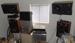
I got a chance to play around with my amps some more today. I think I finally found what everyone was excited about. As I bumped up the volume of each amp the AX started to gain on all the others. The louder I drove it, the better it sounded. A couple of the other amps started clipping or sounded brassy but the Aleph really started to get nice. Pretty surprising that the weakest of the bunch shined the most when played loud. Very nice. These are the amps I was playing with. ES P101, Leach Low TIM, Symasym 5. Krell KSM 50 clone and of course the A-X. What fun!
Attachments
Pass DIY Addict
Joined 2000
Paid Member
") Every now and then, I feel guilty about needing to installing a dedicated 30A breaker and a run of 10 gauge wire to power my trio of Aleph-X amps...
Every now and then, I feel guilty about needing to installing a dedicated 30A breaker and a run of 10 gauge wire to power my trio of Aleph-X amps... hello
for some newbie
where to buy aleph-x pcbs
found information about hifizen boards but no information about any store or ebay auctions
kk boards are morally questionable to buy
could you recommend me any place to buy two for aleph-x high powered monoblock amp?
thx in advance
greetings
5hinka
for some newbie
where to buy aleph-x pcbs
found information about hifizen boards but no information about any store or ebay auctions
kk boards are morally questionable to buy
could you recommend me any place to buy two for aleph-x high powered monoblock amp?
thx in advance
greetings
5hinka
Pass DIY Addict
Joined 2000
Paid Member
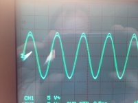
Aleph-X, Asymetric waveforms from output
Input is a 1khz sine wave. I measured the outputs (one side connected to Ch1, the other side connected to Ch2, Ch2 is inverted and superimposed over Ch1) - There is a slight difference in amplitude and waveform shape.
I have 180mv across the output and about 90mv from each output to ground - can't seem to reduce these offsets (I'm guessing at this being due to FET differences at the bias current, mine were matched at a lower current). I can play with these later.
I had amplitude differences previously but searched through the forums and found that driving the amplifier from a single ended input could cause this (increasing the value of the "Macmillan" resistors reduces the effect but with side effects elsewhere (i.e. start-up DC offset)), so I added a DRV134 single ended to balanced convertor and tried to drive the AX inputs directly from that (i.e. without additional coupling capacitors) - I have already checked the amplitude of the DRV134 outputs and they are correct (so inputs to AX are definitely of the same amplitude).
I would greatly appreciate some assistance in trying to resolve this issue.
Attachments
- Home
- Amplifiers
- Pass Labs
- Aleph-X builder's thread.