Cleared last issue after excluded factors - left RCA in and GND were reverted. Fixed and works flawless.Thanks to all of your help, and I sort out both bias and offset after using 2.7 + 2.7 zener (that gave me 5.2 drop after 30 minutes stabilized warm up). Do not use the 1.3W version (that gave me 3.8V drop), 0.5W version works (why?)
Both side stabilizes at 488mw Bias at R2 =0.47Ohm and -1 to 3mV offset. Offset reading changing every few seconds (does this matter?)
Now it comes to a very weird problem.
Primary symptom:
If I plug both left and right channel input RCA, right speaker output will get some left channel! I used youtube left right speaker to verify this. Right channel totally normal, left channel, 60% signal on left and 30% on right.
If I only plug in left RCA - left channel speaker output works fine. If I plug in right RCA, left speaker and right speaker works well. Above problem only happens if plug in both.
Diag:
Offset changing every few seconds at 1-2mV (does this matter?) with no input plugged in.
If left RCA unplugged from source (preamp), there is a buzz on left speaker. Right speaker has no buzz if right RCA unplugged from source (preamp).
Amp totally quite if RCA unplugged at amp side, either side or both.
I suspect it was my preamp problem - tried the following:
Use WHAMMY as preamp, left cross to right happens (verified ok with headphone - they are directly connected with a wire to RCA).
Same symptom happens - left cross to right happens if I use Pass ACA+ preamp (headphone works fine).
Then I changed to a commercial preamp:
Schiit Jotonhaim, [computer => usb => schiit bifrost II => either RCA or XLR=> schiit jot => RCA output => amp). Left speaker channel has NO sound. Right speaker normal.
Any clue for me to continue diag here?
Symptom recap
DIY preamp:
Left speaker output has some power (30% or so) crossed to right speaker out put if and only if both RCA input are plugged. If only one RCA input plugged, that side of speaker output sounds good at full volume.
Commercial amp: no sound on left channel
Right heatsink is about 1.2-1.5CC higher than left - consistent.
Checked solder point - good (topped off left RCA ground on F6 board, not the case).
The common part is PSU, ensure connection are solid and voltage stabilizes 23.1V - 0 -minus 23.1V at working temp (heat sink 39-41.5C).
Given both board drew from almost the same V+ GND V- (and grounding well), power should not be the case.
Check RCA socket insulation, resistance is not infinite nor zero, no matter at 2000K Ohm MM range or 200Ohm MM range. RCA left + and RCA right+ has same resistance as RCA left GND and RCA right GND, in MM range 2000K Ohm (reads 47K), 200K (reads 47K), 2000 (reads 18xx OHM) 200 (reads another number, but same). RCA socket insulation should be good.
Switched left and right speakers - that's not the problem (speakers are KEF LS50 first version)
Where could be it wrong?
Something with the amp
something with the source (preamp)
any suggestions how I can further pin point the problem.
Other devices I have:
Rega Elicit R (has a preamp function build it).
Chord Qutest DAC.
A turntable with Phono preamp.
However, the only way to repro these is to use the speaker left right testing. I could hear left channel of lower volume (and some fuzzy noise) - this might be a little hard using a turntable.
Will give a try using qutest + rega build in preamp tomorrow. Famiily sleeping now.
Many many thanks to all the nice helps. Cheers.
Hi
I've got my F6 boards and am about to order the 3U 400 case from Modushop.
1. They need CAD drawing for the rear panel. Can someone please share? I'd prefer to have them do the drilling. It has 2 RCA, an IEC socket with fuse and 2 banana jacks.
2. I've got a locally built toroid has an OD of 140mm and 60mm height and didn't come with any mounting hardware. How and what hardware do I need to mount it onto the base plate?
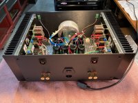
3. I'm not using the standard diyAudio boards. I have the board layout but don't know what is a good position to mount on the heat sinks. For example in the below pic what should be the distance from top and sides of the heatsink to the top right hole on the R channel? The 3U x 400 heatsink will be 120mm x 400mm.

I've got my F6 boards and am about to order the 3U 400 case from Modushop.
1. They need CAD drawing for the rear panel. Can someone please share? I'd prefer to have them do the drilling. It has 2 RCA, an IEC socket with fuse and 2 banana jacks.
- The IEC socket is one with the fuse needing a cutout of 28mm x 47mm plus the holes for the screws.
- The RCA jacks would need 9mm dia holes.
- The speaker binding posts need 8mm dia holes.
2. I've got a locally built toroid has an OD of 140mm and 60mm height and didn't come with any mounting hardware. How and what hardware do I need to mount it onto the base plate?
3. I'm not using the standard diyAudio boards. I have the board layout but don't know what is a good position to mount on the heat sinks. For example in the below pic what should be the distance from top and sides of the heatsink to the top right hole on the R channel? The 3U x 400 heatsink will be 120mm x 400mm.
Reconsider bigger heatsinks for hot summer days.
https://modushop.biz/site/index.php?route=product/category&path=243
https://modushop.biz/site/index.php?route=product/category&path=243
I have an F5 amp at the moment that I like a lot. The best I have ever had.
Can anybody who has made or heard both F5 and F6 give a subjective evaluation which one sounds the best?
My thought is to build a balanced mono block version of the F6. I suppose it is quite easy to convert the differential input stage to a balanced
input.
Thanks in advance
Arthur.
Can anybody who has made or heard both F5 and F6 give a subjective evaluation which one sounds the best?
My thought is to build a balanced mono block version of the F6. I suppose it is quite easy to convert the differential input stage to a balanced
input.
Thanks in advance
Arthur.
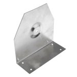
Get the 4u deluxe case with back panel kit. All holes drilled, hardware and switch,sockets etc. use strong tie angle bracket from lowes or Home Depot for transformer. this puts the transformer upright and gives you more room for diodes etc.Thanks for pointing that out. I will get a 4U case.
I have both and the F5 is gathering dust. My two cents, but remember amps are very system dependentI have an F5 amp at the moment that I like a lot. The best I have ever had.
Can anybody who has made or heard both F5 and F6 give a subjective evaluation which one sounds the best?
My thought is to build a balanced mono block version of the F6. I suppose it is quite easy to convert the differential input stage to a balanced
input.
Thanks in advance
Arthur.
Here is a picture of my f3 showing the bracket, just make one yourself. Save your own hardware for another project you know there will be one!I already have the RCA, fuse and binding posts. I'm based in India so Lowes/Home Depot is not an option.
Attachments
If the choice is between 4U/300 vs 3U/400 I would probably go with 3U/400, for better spacing of the mosfet on the heatsinks and more distance between the power transformer and the input transformers.
From a dissipation perspective they should be similar.
Of course, 4U/400 should be even better.") And you can just ask for the 4U back panel drill pattern, assuming that works with the parts you already have..
And you can just ask for the 4U back panel drill pattern, assuming that works with the parts you already have..
From a dissipation perspective they should be similar.
Of course, 4U/400 should be even better.
And you can just ask for the 4U back panel drill pattern, assuming that works with the parts you already have..Shipping to India via FedEx is expensive ($75 from diyAudio and about 100 Euros from Modushop) and duties+taxes is 42%. So every penny I save counts.
The Deluxe 4U costs $414 shipped to me vs the Deluxe 4Ux400 with 4mm front plate from Modushop costs me about $336. I see that diyAudioStore has the back panel with drilled holes for $11 but that only works with Aluminium covers. So getting drilled holes from Modushop may be cheapest.
The 3U/400 would be ideal price wise but will move to the 4U/400 if heat is an issue as I don't want the amp burning out. But still prefer to keep the costs down as much as possible.
@Dennis Hui if dissipation wise both are equal, that's awesome. Who do I ask for the 3/4U back panel drill pattern?
atharva,
Here you go with a pic of a mounting bracket and a link with some more details.
Possibly you can have this made locally in India.
https://www.audiophonics.fr/en/tran...t-for-toroidal-transformer-o150mm-p-6039.html
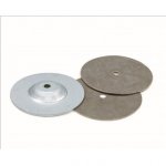
If your transformer does not have a potted core you will need some other mounting hardware to hold it in place - some images provided of the hardware and also how 6L6 used the mounting bracket and hardware for his F6 build.
If I may ask, which state are you located in?
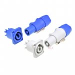
Regarding drilling holes in the back plate if the chassis, in my experience, drilling circular holes are quite easy, whereas the rectangular hole for the IEC is more difficult. One idea of avoiding an IEC socket is to you a Powercon connector - an image provided for your reference.
Here you go with a pic of a mounting bracket and a link with some more details.
Possibly you can have this made locally in India.
https://www.audiophonics.fr/en/tran...t-for-toroidal-transformer-o150mm-p-6039.html
If your transformer does not have a potted core you will need some other mounting hardware to hold it in place - some images provided of the hardware and also how 6L6 used the mounting bracket and hardware for his F6 build.
If I may ask, which state are you located in?
Regarding drilling holes in the back plate if the chassis, in my experience, drilling circular holes are quite easy, whereas the rectangular hole for the IEC is more difficult. One idea of avoiding an IEC socket is to you a Powercon connector - an image provided for your reference.
Attachments
Last edited:
Thanks @zman01
I'm in Pune, Maharashtra.
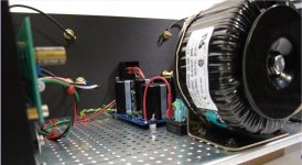
I did a mockup of the layout of items inside the 3U case with the toroid flat on the bottom, PSU and softstart board. I could orient the softstart board vertically if needed.

Mockup of the back panel. Does the spacing look fine? Top 2 holes are RCA, bottom are speaker binding posts and the IEC socket in the middle. Ignore the dotted lines.

This is for the heatsink. Is the spacing ok? I get 42mm from the top and 31mm from the bottom. 90mm towards the rear of the chassis and 80mm towards the front.

I'm in Pune, Maharashtra.
I did a mockup of the layout of items inside the 3U case with the toroid flat on the bottom, PSU and softstart board. I could orient the softstart board vertically if needed.
Mockup of the back panel. Does the spacing look fine? Top 2 holes are RCA, bottom are speaker binding posts and the IEC socket in the middle. Ignore the dotted lines.
This is for the heatsink. Is the spacing ok? I get 42mm from the top and 31mm from the bottom. 90mm towards the rear of the chassis and 80mm towards the front.
Atharva,
Your layout in the first image looks ok - however, I have a question: Where are you planning to place the power on/off switch?
I see that you have 15mm gap from the edge of the toroidal transformer to the front panel; if you are planning to place the power switch on the front, then depending on the thickness of the panel, the size of the switch, and placement of the switch, 15mm might be too less. After mounting a power switch on the front panel, the body of the switch and tabs/connectors tend to stick out; and you also need to connect the wires from the IEC socket and power transformer to the tabs on the switch. If the power switch will be on the back, then it should not be an issue.
Comments on the second image - I see that the speaker connector centers are placed 60 mm and 100 mm from the respective outer edges of the back panel; you can possibly make it 50mm and 90 mm from the edges, so that there is a little more distance from the AC power inlet. The RCA connectors would then also shift 10mm closer the edges and away from the center.
I recall you mentioning that you are using a different PCB vs the diyAudio store ones? Maybe not super important, but my bias would be towards placing each of the output devices (IRFP240 MOSFET) at horizontally equal distances from the edges; the PCB may or may not be symmetrically placed, but the output devices will be. If you are using a Modushop case, then it is possibly 2 x 200mm sinks?
31mm distance shown from the bottom of the heatsink is for the edge of the MOSFET? that looks fine. If it is the edge of the PCB, will the MOSFET be mounted at the edge of the PCB like the diyAudio Store PCBs? If that is the case, the MOSFETs will be closer to the bottom of the heat sink.
- Z
Last edited:
- Home
- Amplifiers
- Pass Labs
- F6 Illustrated Build Guide