I just tried to set up the bias and offset on my newly-built F6 and got a very unwelcome surprise.
(I had previously checked the power supply, ramping up slowly with a Variac until I got +24 vdc and -24 vdc, then let the power supply run for a couple of hours: No problem. I had also previously set the bias and offset pots to minimum R, as detailed by Zen Mod--measured for P1 from wiper to gnd, and for P2 from wiper to neg. rail.)
Turning on the power for one channel only, I heard a crackle and then saw flame on the Q3/Q4 input pair !! ( the Qs were touching each other, as shown in 6L6's example photo)
Neither the meter on bias, nor the meter on offset ever budged from 0 vdc. I blew out the flame on the plastic bits of the Q3/Q4 pair, and killed the AC power immediately. The input Qs are now toast, and R5 (1K) looks cooked too.
Before I start tearing things apart to search for my error, I have a question. For some reason (I don't know why; 6L6 never said to do this!) I had inserted a shorting plug on the RCA input prior to the set up procedure: A zero-ohm shorting plug. Is it possible that this could have caused the destruction? (I don't see how, but I've already demonstrated that I'm not the sharpest tool in the shed.)
Thanks for any help that folks here can offer. My Zen V4, and my F5 both took off and flew their maiden flights with no problems. This time, I never got off the runway without disaster striking.
pictures might be helpful in diagnosing.
Did you double check Q3/Q4 to make sure correct JFETs were in the correct positions? (no fireworks but I did fry mine because of this mistake.)
Orientation of the zeners correct?
Anything else toasty?
Did you double check Q3/Q4 to make sure correct JFETs were in the correct positions? (no fireworks but I did fry mine because of this mistake.)
Orientation of the zeners correct?
Anything else toasty?
Thank you aljordan and 6sX7 for your responses. I did wonder after the flame was out if I could have reversed the relative position of the JFETS. Its not something I would have easily caught during a review of the stuffing job, since the identifying codes on the Qs were obscured by orienting the flats of the devices and pressing them together. Wouldn't be my first polarity error in this hobby! Never actually saw flame before, however.
I'll have to pull the board out of the amp to find and fix the problem(s), so I'll take some clear closeup pictures when I've got it out. Pretty sure the zeners are in right now, since I had them in backwards initially, before I finished stuffing the boards, and had to redo them (with new units) so that the banded cathode end of each was placed in agreement with the banded end on the silkscreen.
I'll have to pull the board out of the amp to find and fix the problem(s), so I'll take some clear closeup pictures when I've got it out. Pretty sure the zeners are in right now, since I had them in backwards initially, before I finished stuffing the boards, and had to redo them (with new units) so that the banded cathode end of each was placed in agreement with the banded end on the silkscreen.
check that the + and - rails didn't get mixed - sounds silly but I've done myself with rather spectacular results with the electro caps, not jfets ...
Turning on the power for one channel only, I heard a crackle and then saw flame on the Q3/Q4 input pair !! ( the Qs were touching each other, as shown in 6L6's example photo)
That does rather sound like the result of wrong polarity connection from the power supply.
(Don't ask how I know that!) 🙄
Last edited:
Thanks jameshillj and ColinA123 for your contributions to my F6 effort. I double checked the power supply polarity and found that it was correct. I am becoming more and more convinced that the Q3 and Q4 units were not positioned correctly. I pulled them out of the circuit and attempted to verify this, but they were "burned beyond recognition", as we say. No markings visible on the charcoal like surface! I haven't yet checked pair on the other channel, which was not powered up at the time of the mishap. And even if the pair on that channel is oriented correctly, I still could have screwed up on the channel that gave up the smoke. Nothing else on that affected channel seems to have been destroyed, by the way. The nearby resistors all seem to be okay upon examination.
I went ahead and ordered another NP matched quad Q set from the diyAudio store, and will continue with board scrutinizing before I install them (and only then after triple checking that the Q3/Q4 placement is correct this time!). Sigh!... Another expensive lesson learned (hopefully).
Historical note: Thirty years ago I had finished up the build on my third Leach Low-TIM amplifier (AUDIO magazine; Feb. 1976 article by W. Marshall Leach) and was about to set the bias on the output transistors. I had my then-10 year old daughter standing by with a fire extinguisher. "If you see flames, just let fly with the extinguisher," I instructed. I turned on the AC power switch (didn't have a Variac at that point) and.....nothing. No pilot light, no reading on my Beckman multimeter. Nothing. Nada. I started to moan and groan about another project failure. Until my daughter pointed and said, "Dad! It's not plugged in!". Embarrassed, I remedied the oversight, and the amp powered up. I set the bias, and everything was fine. The amp has been driving my home built TL subwoofer ever since.
Is it relevant if the Washers for clamping down the Transistors are magnetic or not? Did anybody investigate that?
Last edited:
I took pains to verify that the M3 screws and washers wasn't magnetic. How much difference it does I don't know, but why not?
Slightly off topic: In the 90's a friend and I did some testing of magnetic conductors in signal cables and phono contacts that was directly in the signal path and we could clearly identify the effect magnetic parts had on the sound.
Slightly off topic: In the 90's a friend and I did some testing of magnetic conductors in signal cables and phono contacts that was directly in the signal path and we could clearly identify the effect magnetic parts had on the sound.
I used these on my F6 instead of washers. Not sure how much they do as far as dissipating heat but they aren't magnetic and are relatively affordable. I keep a bunch of them around for different projects.
https://www.mouser.com/ProductDetail/Aavid/504222B00000G?qs=XF/z8BtdrptQos6B0WOfeg==
https://www.mouser.com/ProductDetail/Aavid/504222B00000G?qs=XF/z8BtdrptQos6B0WOfeg==
I use transistor clips like the Aavid KU-4-448 and 449 - very even pressure and ease of assembly
Also, an interesting test. I played around trying different MOSFETs at different bias levels over the last few weeks.
IRFP240
IRFP150
FQH44N10
IRFP240's sound nice but the IRFP150's are more detailed. I tried the FQH44N10's but were less detailed on top than the 150's. They also had less soundstage and imaging. I couldn't quite get that with the FQH's. I think the FQH's had more bass but that is generally not at the forefront of my mind.
Although it didn't work out for me with the FQH44N10's, I am glad I tried them. I burned them in for over a week using them in the interim. I tried to give myself time to get used to them. I eventually put the IRFP150's on one channel, FQH's on the other, swapped speaker leads, inputs, walked up to each speaker and listened very carefully. I even had my wife swap the leads and not tell me what was what. The IRFP150's were certainly better on the highs which is very important to me.
Has anyone else played with some interesting output devices? It is like a really involved form of tube swapping... At least the parts are quite cheap.
Following up on my post #4027 above. My new NP JFET matched quad arrived from the diyAudio store a few days ago. I also got a shipment from Mouser with 3K3 ohm resistors for R7 and R8, and 6 volt Zeners. I installed all these parts on both Channel A (the one that turned the Q3/Q4 pair into little charcoal briquets. See post #4021) and Channel B. In the meantime, I examined both boards for questionable soldering, measured resistors, checked transformer pins, looked for shorts and other obvious assembly errors.
After these changes, I was able to successfully bring the B channel up, with only a couple of millivolts of offset, and about 510 millivolts of bias! But the firebug A channel refused to bias beyond about two millivolts. Since the only things unchanged at this point were the power MOSFETS Q1 and Q2, I started to focus on those. I ordered a quad set of MOSFETs from the diyAudio store (and yet another set of JFETs, just in case). They will all arrive Monday.
In the meantime, I looked closer at Q1 and Q2, using my multimeter, and got some screwy results when attempting to check the transistor junctions with the diode test function on my Beckman 310, while the devices were still in the circuit. So, I unsoldered Q1 and removed it from the circuit board and tried again. My meter read "OL" (overload) on the Gate to Source junction test for this Q1, regardless of orientation of the probes. The booklet for my meter says " If OL is displayed with both lead connections, the junction is open". (To perform this test, the meter uses a constant-current source to force 5mA of current into the semiconductor junction, which results in the voltage drop being displayed" [normally 600 to 900mV]).
Question: This meter dates from 1979, and the examples shown in the booklet pertain to bipolar NPN and PNP transistors. Can I assume that a meter reading outside of the normal range of junction voltage drop would be applicable to power MOSFET devices as well? What about the JFETs?
It's late here now, so I won't be able to get the Q2 unit unsoldered and tested until tomorrow at the earliest. But I'm wondering if an open G-S junction on Q1 would be enough to result in my inability so far to bias the A channel beyond a couple millivolts. I guess I'd better check the G-D junction on the Q1 unit as well, right?
Thanks for your help!
Magnetic - bad. The sound lacks top end definition and clarity, a bit smeared.Good, bad or how different?
A very telling case was(is) the RG62 coax cable that was very popular at some point as a signal cable. When we replaced that for another coax (forgot the name) with copper wire in the center the difference was telling. This started our investigation of the cause and several sources attributed the magnetic wire as the main factor.
Thanks for the evaluation, very useful. Now I would really like to try out different MOSFET's. I use FQH44N10 and as you say, they have an impressive bass because I use my F6 for movie sound as well as for pure audio. Having better imaging and soundstage is very appealing, after all this should be the strength os a Pass amp....
IRFP240's sound nice but the IRFP150's are more detailed. I tried the FQH44N10's but were less detailed on top than the 150's. They also had less soundstage and imaging. I couldn't quite get that with the FQH's. I think the FQH's had more bass but that is generally not at the forefront of my mind.
...
Has anyone else played with some interesting output devices? It is like a really involved form of tube swapping... At least the parts are quite cheap.
I will have to do some thinking on how to be able to plug in different output transistors without soldering. Anyone else done that?
Cool, it would be interesting to see if someone else has similar thoughts after trying it. I was thinking short leads that would still have to be soldered on but would at least get the MOSFET off of the circuit board.
I'm not getting anywhere with my F6.
With both Q1 and Q2 unsoldered/removed from Chan A, I find that I am at a loss to see why that channel would not bias. I tested the Q1 and Q2 units I had suspected, as well as a new Q from a matched quad of N types that I got this week from the DIY store. I used the test circuit published by Papa in 1993, with a 15vdc regulated supply and about 50 ohms in series. I did this because his article said "this test will also tell you whether or not the device is broken."
I got these results:
Vgs
Q1 4.08
Q2 4.04 *see note
Q brand new 4.02
*Note: even when the voltage was removed, the Q2 unit showed a residual 0.87 Vgs, which persisted for a long time. I assume this reflects the build up of capacitance at the gate. Does that seem reasonable?
Since these measurements all appear to be in the expected range, I concluded that the devices are functional. (Oddly, only Q2 had a residual charge as noted).
With no power MOSFETS to blame. I am back to square one. As I did earlier in the week, I went back over everything in Chan A looking for poor solder joints or solder "bridges", misplaced or suspect resistors, misaligned diodes, other burn victims from my initial Q3/Q4 flameout, etc. I measured the transformer windings ("in situ," as ZM says) and got 14 ohms between pins 1 and 3, and between pins 2 and 4. I got 28 ohms between pins 5 and 7, and between pins 6 and 8. I don't see an bad solder joints, but haven't reflowed the entire board yet, since I worry about too much heat for those tiny JFETS and zeners (6.0 V). The 5K bias and offset trimmers react to my screwdriver turns with the expected changes in resistance across their range. They are now back at their initial lowest resistance readings, relative to the correct points.
I have not tried any voltage or current measurements under power, beyond the failed effort at setting bias and offset mentioned in my earlier post.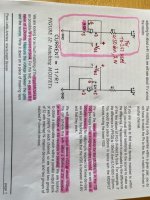
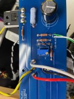
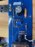
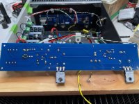
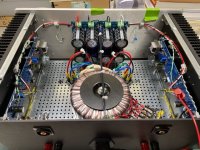

I don't know what to do at this point, other than starting another Chan A build from scratch with all new parts!
Any further suggestions from fellow DIYers would be greatly appreciated!
Zapped (and feeling trapped!)
With both Q1 and Q2 unsoldered/removed from Chan A, I find that I am at a loss to see why that channel would not bias. I tested the Q1 and Q2 units I had suspected, as well as a new Q from a matched quad of N types that I got this week from the DIY store. I used the test circuit published by Papa in 1993, with a 15vdc regulated supply and about 50 ohms in series. I did this because his article said "this test will also tell you whether or not the device is broken."
I got these results:
Vgs
Q1 4.08
Q2 4.04 *see note
Q brand new 4.02
*Note: even when the voltage was removed, the Q2 unit showed a residual 0.87 Vgs, which persisted for a long time. I assume this reflects the build up of capacitance at the gate. Does that seem reasonable?
Since these measurements all appear to be in the expected range, I concluded that the devices are functional. (Oddly, only Q2 had a residual charge as noted).
With no power MOSFETS to blame. I am back to square one. As I did earlier in the week, I went back over everything in Chan A looking for poor solder joints or solder "bridges", misplaced or suspect resistors, misaligned diodes, other burn victims from my initial Q3/Q4 flameout, etc. I measured the transformer windings ("in situ," as ZM says) and got 14 ohms between pins 1 and 3, and between pins 2 and 4. I got 28 ohms between pins 5 and 7, and between pins 6 and 8. I don't see an bad solder joints, but haven't reflowed the entire board yet, since I worry about too much heat for those tiny JFETS and zeners (6.0 V). The 5K bias and offset trimmers react to my screwdriver turns with the expected changes in resistance across their range. They are now back at their initial lowest resistance readings, relative to the correct points.
I have not tried any voltage or current measurements under power, beyond the failed effort at setting bias and offset mentioned in my earlier post.


I don't know what to do at this point, other than starting another Chan A build from scratch with all new parts!
Any further suggestions from fellow DIYers would be greatly appreciated!
Zapped (and feeling trapped!)
- Home
- Amplifiers
- Pass Labs
- F6 Illustrated Build Guide
