Don't feel too bad. I'm still in the same position with the left channel. We will both get there. HeyBill
Thanks HeyBill for the encouragement.!
When I look at how these photos posted, it is apparent that I should have chosen a higher resolution. Trying to enlarge them to see what the heck the solder jobs look like, or what the resistor markings indicate is pretty fruitless. I was worried that my standard iPhone photos would take up too much capacity and get rejected. Next time I will attach bigger files.
When I look at how these photos posted, it is apparent that I should have chosen a higher resolution. Trying to enlarge them to see what the heck the solder jobs look like, or what the resistor markings indicate is pretty fruitless. I was worried that my standard iPhone photos would take up too much capacity and get rejected. Next time I will attach bigger files.
Zapped,
I don't know if this will help, but can you do a few measurements?
First, confirm the voltages across the zeners Z1 and Z2.
Then try measuring the Vgs voltage across the output mosfets. (The voltage between the two outer pins)
Try adjusting P1 when measuring Q1 and see if the measured voltage changes. Do the same with P2/Q2.
The idea here is you should be able to get these measured voltages into 4-ish volt range by adjusting P1 and
P2 and get the mosfets on.

Thank you for the idea, Dennis! I will solder the MOSFETS back on the board tomorrow, and see what results I get for these measurements.
Finally got around to mounting the transformer vertically which gave me space to move the filter board forward and declutter some things. Got one channel running with the new filter board and the CL-60 soft start circuit finally implemented. 18,000 uF 50V 105C caps rated for 8k hours. Will get the other channel upgraded. After that, some fully stuffed rectifier boards to replace the discrete bridges.


Last edited:
Dennis: When I started to put my old Q1 and Q2 units back on the A channel board to make these measurements, I realized that I wouldn't be able to attach my little mini-grabber meter probes to their gate and source pins, because I had snipped those off at the top of the board when I first assembled the amp. And there isn't enough clearance under the board to fit the probes to the gate and source leads there. So I got two of the brand-new MOSFETS I received from the diyAudio store last week and soldered them in instead, but this time leaving the pin ends untrimmed.Zapped,
I don't know if this will help, but can you do a few measurements?
First, confirm the voltages across the zeners Z1 and Z2.
Then try measuring the Vgs voltage across the output mosfets. (The voltage between the two outer pins)
Try adjusting P1 when measuring Q1 and see if the measured voltage changes. Do the same with P2/Q2.
The idea here is you should be able to get these measured voltages into 4-ish volt range by adjusting P1 and
P2 and get the mosfets on.
Once I had everything in place, however, I powered up the A channel and, before making the measurements you suggested, tried one last time to set the bias and offset using the standard procedure. I turned that bias pot screw about 19 or 20 times with no visible effect, and was about to give up, when I saw the meter across the .47 ohm resistor finally react! I was able to increase the bias, and alternate with offset adjustments, over the next half hour or so, reaching about .510 mV bias and just a couple of mV of offset on the output terminals! Success!!
Since the old Qs seemed to test OK outside of the amp, I figure either I had a bad solder joint on my first iteration, or my first-run pot adjustment procedure was flawed. Either way, I am overjoyed to now have a functioning amp.
Thank you for your interest, and for your help, Dennis. Without your suggestion to measure Vgs at the Q pins, I probably would have just tossed the old clipped units back onto the board, and who knows where I'd be then.
Zapped
aka
Larry Wright
Camas, WA USA

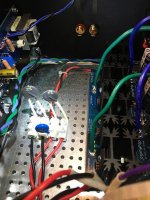
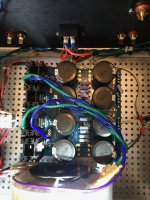
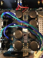
Today I fired up the power supply on my F6 kit for the first time. There is no connection from the power supply to the F6 amp boards yet. I ran the mains power through my dim bulb tester, which glowed bright then dimmed to off. Nothing exploded but one of the LEDs (the negative voltage channel) did not light so I turned everything off right away. The fuses on the AC input to the amp did not blow. I searched for a reason why the LED did not light and for shorts but nothing was obvious. However, I am not certain what I am looking for either. Both LEDs are connected with proper polarity ie. negative leg to ground. I Did some testing looking at continuity and noticed there seemed to be continuity between the grounds on the power PCB and both the plus and minus voltage connections on the power PCB. Then I noticed that the readout on the meter started low and grew higher so I suspect the current from my meter is charging the capacitors. Maybe that is ok?
So at the moment I only know that the led on the negative rail does not light. Is it possibly just a damaged LED?
I would really appreciate it if someone could look at the pictures I have attached of the power supply to see if everything appears to be in order. I a bit nervous about a second try with power, really don't want to fry anything if possible.
The negative voltage channel for which the LED did not light is the lower one as shown in img_1360, 1361, 1363.
If it had powered up without incident I was going to check for a DC voltage across the V- to Grnd and the V+ to Grnd looking for something around 23 volts in each case. Is that correct and are any other tests recommended before connecting the first amp board?
Attachments
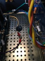

Both LEDs are connected with proper polarity ie. negative leg to ground.
That's incorrect. The negative (cathode) leg has to go to the 'lower voltage' side.
So for the positive rail, for anode goes to the V+ and the cathode to GND.
For the negative rail, the anode goes to GND, and the cathode to V-.
Edit: For the voltage measurement, with the COM / black probe on GRD, you should measure about +24V with
the red probe at V+, and about -24V with the red probe at V-. The exact value isn't too important.
Last edited:
Dennis,
Thanks! That must be my problem. Do you think if I reverse the offending LED it will work or should I replace it? Is it likely I damaged anything else?
Thanks! That must be my problem. Do you think if I reverse the offending LED it will work or should I replace it? Is it likely I damaged anything else?
6sX7 Just wondering if you are old enough to remember Curly of the Three Stooges when he would say "Oh! A wise guy?"
So taking the sage advice of the honorable 6sX7, both leds lit up and 24.4 volts was measured at each the negative and positive rail. Color me happy. Many Thanks again. Onward!
I wasn't going to expound eloquently as an excellent experimentin' experience was to be enjoyed. Voltages are low enough that it shouldn't have been hurt and no harm would be had in just trying. Besides, I did the same exact thing on one channel of the F6 boards due to the asymmetrical layout.
Having started with the B+ of vacuum tubes, I keep having to remind myself to experiment a bit. Have to be cognizant of the heat issues that high current brings, but take some relief in less concern with getting bit by the likes of 500VDC.
Having started with the B+ of vacuum tubes, I keep having to remind myself to experiment a bit. Have to be cognizant of the heat issues that high current brings, but take some relief in less concern with getting bit by the likes of 500VDC.
My PSU is ready and am getting 26V on the rails. The board says 23V and the original post by 6L6 mentions 24V. Is 26 going to be bad or is it fine with some adjustments to the bias / temperature (may be get hotter) expectations? Would I still look for the 0.5V across R2?
.5 is a starting point. Adjusting based off of the parameters set by 6L6 in the OP, you will likely end up between .590 and .640. I keep mine at .625. The center pin of the mosfets staying under 65 degrees celcius is the limiting factor.My PSU is ready and am getting 26V on the rails. The board says 23V and the original post by 6L6 mentions 24V. Is 26 going to be bad or is it fine with some adjustments to the bias / temperature (may be get hotter) expectations? Would I still look for the 0.5V across R2?
- Home
- Amplifiers
- Pass Labs
- F6 Illustrated Build Guide