voltage
that's certainly more precise measurement than temperature
few C of difference , just ignore it
that's certainly more precise measurement than temperature
few C of difference , just ignore it
Request help: zero voltage bias no matter what
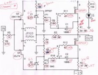
r1 0.56 ohm zero voltage drop
r2 0.47 ohm zero voltage drop
adjusted p2 and then p1, no change
no heat generated at all.
Diag so far
power input 25.7 - 0 - (-25.7) v verified, without amp board, psu output was 26.0v.
both 5.1 zener shows a voltage drop of 4.1v
Both resistors beside zener 21.1v
p1 and p2 pot are measured 3.28k ohm total, come with a kit, not 5k pot, problem?
power grounding wire is 19awg, not 16awg used for v+ and v-, problem?
both transistors pin 2-1 drop 25v, pin 2-3 drop 22.8v expected?
led light up 1.8v drop -red, led resistor 23.7v
ALL other resistor shows 0 voltage drop. Capacitor is spec 25V - should be ok.
Any suggestion? thanks a lot.
Excluded pot - 502 tells me 5k, measurements is a result of other parts on circuitRequest help: zero voltage bias no matter what
r1 0.56 ohm zero voltage drop
r2 0.47 ohm zero voltage drop
adjusted p2 and then p1, no change
no heat generated at all.
Diag so far- 2 boards the same.
power input 25.7 - 0 - (-25.7) v verified, without amp board, psu output was 26.0v.
both 5.1 v zener shows a voltage drop of 4.1v
Both resistors beside zener 21.1v
power grounding wire is 19awg, not 16awg used for v+ and v-, problem?
both transistors pin 2-1 drop 25v, pin 2-3 drop 22.8v expected?
led light up 1.8v drop -red, led resistor 23.7v
ALL other resistor shows 0 voltage drop. Capacitor is spec 25V - should be ok for 26v.
Any suggestion? thanks a lot.
View attachment 1009483
Sorry for the problems. Just powered F6 yesterday and ended up working. However thought something was wrong on power up as no heat even after some "CONSERVATIVE" adjustments of P2 bias. Ended up having to turn the P2 pot quite a number of turns, then holy cow voltage came up fast. As was said by others be patient on the adjustment of P2. Did nothing the first 30 minutes but adjust the P2 Pot to .500 volts bias on both sides.Excluded pot - 502 tells me 5k, measurements is a result of other parts on circuit
Then went on to the offset. Turning P1 pot clockwise lowered the voltage. Interesting was turning down the voltage of P1 had to go back and turn down voltage using P2. Did this a number of times. Even when thought I was done had to turn down voltage through P1 pot.
5K pots measured 2.5k on insertion into board.
Z1,Z2--used 6.2 volt zeners.
R7,R8 used 3.3kohms
There was a large conversation going about zener values and R7,R8 values. There seem to be changes all the time when someone (A lot smarter than me) came to conclusions.
Maybe these values affected the way the bias responded to adjustments.
I don't have answer for you but maybe just reading something will make your mind click and say "Oh yea". Beat of luck and sure the masters of engineering will chime in and help you at some point.
I failed at the Aleph J a few years ago even with excellent tips. WIll go back to that at some point to fix it. The F6 sounds great to me. I am older and somewhat hard of hearing but with ear right next to speaker with out input heard absolute silence. Good luck
Attachments
Since neither of the IRFP240 mosfets are heating up, I would suspect that it would be a common issue would be with the power supply. Have you confirmed that you have the power supply leads hooked up to the board correctly? If there was a issue with one of the pots, zeners or other components in the bias circuit, that would likely only effect one misfit.
You have to turn the pots quite a few times to get the bias to start coming up. I believe they are 25 turn trimmers or something like that.
You have to turn the pots quite a few times to get the bias to start coming up. I believe they are 25 turn trimmers or something like that.
I find ine 12awg wire that is just long enough to hook one side ground (replace the 19awg). Ordering more. 19 awg should just work.Request help: zero voltage bias no matter what
r1 0.56 ohm zero voltage drop
r2 0.47 ohm zero voltage drop
adjusted p2 and then p1, no change
no heat generated at all.
Diag so far
power input 25.7 - 0 - (-25.7) v verified, without amp board, psu output was 26.0v.
both 5.1 zener shows a voltage drop of 4.1v
Both resistors beside zener 21.1v
p1 and p2 pot are measured 3.28k ohm total, come with a kit, not 5k pot, problem?
power grounding wire is 19awg, not 16awg used for v+ and v-, problem?
both transistors pin 2-1 drop 25v, pin 2-3 drop 22.8v expected?
led light up 1.8v drop -red, led resistor 23.7v
ALL other resistor shows 0 voltage drop. Capacitor is spec 25V - should be ok.
Any suggestion? thanks a lot.
View attachment 1009483
When I crank p2 all the way up, I end up at 0.248v cross R2 - 0.47 Ohm. Still something not right.
Thank you. 25.7 - 0 - minus 25.7V is measured at F6 board. Capacitors are charged up - after powering off, it took a couple minutes for psu to come down to zero - both side at same speed. Every 3s or so 0.1v drop.Since neither of the IRFP240 mosfets are heating up, I would suspect that it would be a common issue would be with the power supply. Have you confirmed that you have the power supply leads hooked up to the board correctly? If there was a issue with one of the pots, zeners or other components in the bias circuit, that would likely only effect one misfit.
You have to turn the pots quite a few times to get the bias to start coming up. I believe they are 25 turn trimmers or something like that.
I’ll continue diag with new grounding wires. It is now half on. Plus, I can have up to 0.128v offset with p1.
Last edited:
Very insightful info, thank you.Sorry for the problems. Just powered F6 yesterday and ended up working. However thought something was wrong on power up as no heat even after some "CONSERVATIVE" adjustments of P2 bias. Ended up having to turn the P2 pot quite a number of turns, then holy cow voltage came up fast. As was said by others be patient on the adjustment of P2. Did nothing the first 30 minutes but adjust the P2 Pot to .500 volts bias on both sides.
Then went on to the offset. Turning P1 pot clockwise lowered the voltage. Interesting was turning down the voltage of P1 had to go back and turn down voltage using P2. Did this a number of times. Even when thought I was done had to turn down voltage through P1 pot.
5K pots measured 2.5k on insertion into board.
Z1,Z2--used 6.2 volt zeners.
R7,R8 used 3.3kohms
There was a large conversation going about zener values and R7,R8 values. There seem to be changes all the time when someone (A lot smarter than me) came to conclusions.
Maybe these values affected the way the bias responded to adjustments.
I don't have answer for you but maybe just reading something will make your mind click and say "Oh yea". Beat of luck and sure the masters of engineering will chime in and help you at some point.
I failed at the Aleph J a few years ago even with excellent tips. WIll go back to that at some point to fix it. The F6 sounds great to me. I am older and somewhat hard of hearing but with ear right next to speaker with out input heard absolute silence. Good luck
So you have a .128v offset? You should have some bias then. You should have received the higher voltage zeners in the kit.
- Z1a/2a 6.0V Zener (4) (Marked "33B")
fengyink,
As others have pointed out, you have an issue with the zener value and the resistors R7 and R8. The 4.1V you measured across
the 5.1V zeners suggests that the zeners are current-starved and not regulating. Changing R7 and R8 to 3 to 5K should address this. (The exact value is not important so just use whatever you might have). Since you are getting some decent current with the pots all the way up, getting the voltage across the zeners to 5.1V might be enough to get the proper bias current. (Though if you already have some 6-ish volt zeners I would just use them).
BTW, with these changes, you need to turn the pots back down before power up, otherwise you risk having the bias current up too high. and damaging the mosfets.
If you have to order the resistors, get 3.3k, 2 picoDumbs has a great bias mod that works well to replace the zeners with a string of 3 LEDs tied together in series. It helps the amplifier to get to opperating BIAS and offset quicker than the Zener setup. If you switch your amp off after use, that would be a nice addition.
dumb-biasing-mod-applicable-to-f6-and-other-papa-amps-possibly-my-dumbest-idea-yet.348969
In post #92, i posted some pics to help understand the mod. The LEDs should light up when facing the correct direction
dumb-biasing-mod-applicable-to-f6-and-other-papa-amps-possibly-my-dumbest-idea-yet.348969
In post #92, i posted some pics to help understand the mod. The LEDs should light up when facing the correct direction
Setting startup bias to minimum is confirmed by turning the bias pots all the way (potentiometer makes slight "click" sound) opposite direction of arrow on the board?
Setting startup bias to minimum is by turning the bias pots all the way (until pot makes a "click" sound) opposite direction of arrow on the board?
I don't trust in arrows at board, even when I drew them
I trust only in DMM - measure what you set (resistance), prior to powering up
I trust only in DMM - measure what you set (resistance), prior to powering up
I'll see if I can figure that out. Not exactly sure what I'm looking for, other than generically either high resistance approaching 5k or low resistance approaching 0, between two important points.
On another note, I see a page or two back an issue about ground loop and hum. Per what I thought the build guide said, I put jumpers at the grounds on the input and output side of the capacitor bank. Is this going to cause a problem such that I should just snip out one of them (the input side??) before I even put it all together?
Attachments
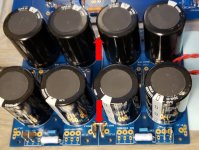
It is Ok to have jumpers at both locations on your PSU board. Pick just one of those locations to connect to the channel boards. Use the GND point near the rectifiers to make the ground lift connection between audio and chassis.
Thanks a lot, folks. 3.3k R7 and R8 solves the bias. I can reach 0.5V bias at R2 = 0.47ohm. Pin 2 stays at 60c. 2.7v zener (and leds) on their way. Sadly, offset stays at -13mV for the final 4-6 turns in p1 and did not go up to zero. I’d assume this is ok given its small and negative? Thanks again.If you have to order the resistors, get 3.3k, 2 picoDumbs has a great bias mod that works well to replace the zeners with a string of 3 LEDs tied together in series. It helps the amplifier to get to opperating BIAS and offset quicker than the Zener setup. If you switch your amp off after use, that would be a nice addition.
dumb-biasing-mod-applicable-to-f6-and-other-papa-amps-possibly-my-dumbest-idea-yet.348969
In post #92, i posted some pics to help understand the mod. The LEDs should light up when facing the correct direction
Thanks to all of your help, and I sort out both bias and offset after using 2.7 + 2.7 zener (that gave me 5.2 drop after 30 minutes stabilized warm up). Do not use the 1.3W version (that gave me 3.8V drop), 0.5W version works (why?)That's an acceptable DC offset.
Both side stabilizes at 488mw Bias at R2 =0.47Ohm and -1 to 3mV offset. Offset reading changing every few seconds (does this matter?)
Now it comes to a very weird problem.
Primary symptom:
If I plug both left and right channel input RCA, right speaker output will get some left channel! I used youtube left right speaker to verify this. Right channel totally normal, left channel, 60% signal on left and 30% on right.
If I only plug in left RCA - left channel speaker output works fine. If I plug in right RCA, left speaker and right speaker works well. Above problem only happens if plug in both.
Diag:
Offset changing every few seconds at 1-2mV (does this matter?) with no input plugged in.
If left RCA unplugged from source (preamp), there is a buzz on left speaker. Right speaker has no buzz if right RCA unplugged from source (preamp).
Amp totally quite if RCA unplugged at amp side, either side or both.
I suspect it was my preamp problem - tried the following:
Use WHAMMY as preamp, left cross to right happens (verified ok with headphone - they are directly connected with a wire to RCA).
Same symptom happens - left cross to right happens if I use Pass ACA+ preamp (headphone works fine).
Then I changed to a commercial preamp:
Schiit Jotonhaim, [computer => usb => schiit bifrost II => either RCA or XLR=> schiit jot => RCA output => amp). Left speaker channel has NO sound. Right speaker normal.
Any clue for me to continue diag here?
Symptom recap
DIY preamp:
Left speaker output has some power (30% or so) crossed to right speaker out put if and only if both RCA input are plugged. If only one RCA input plugged, that side of speaker output sounds good at full volume.
Commercial amp: no sound on left channel
Right heatsink is about 1.2-1.5CC higher than left - consistent.
Checked solder point - good (topped off left RCA ground on F6 board, not the case).
The common part is PSU, ensure connection are solid and voltage stabilizes 23.1V - 0 -minus 23.1V at working temp (heat sink 39-41.5C).
Given both board drew from almost the same V+ GND V- (and grounding well), power should not be the case.
Check RCA socket insulation, resistance is not infinite nor zero, no matter at 2000K Ohm MM range or 200Ohm MM range. RCA left + and RCA right+ has same resistance as RCA left GND and RCA right GND, in MM range 2000K Ohm (reads 47K), 200K (reads 47K), 2000 (reads 18xx OHM) 200 (reads another number, but same). RCA socket insulation should be good.
Switched left and right speakers - that's not the problem (speakers are KEF LS50 first version)
Where could be it wrong?
Something with the amp
something with the source (preamp)
any suggestions how I can further pin point the problem.
Other devices I have:
Rega Elicit R (has a preamp function build it).
Chord Qutest DAC.
A turntable with Phono preamp.
However, the only way to repro these is to use the speaker left right testing. I could hear left channel of lower volume (and some fuzzy noise) - this might be a little hard using a turntable.
Will give a try using qutest + rega build in preamp tomorrow. Famiily sleeping now.
- Home
- Amplifiers
- Pass Labs
- F6 Illustrated Build Guide