James is right, it's not the extra 2 volts of the 20V transformer. ")
You mentioned the ground link on the PCB is solid wire, (just that one is sufficient, assuming it's soldered properly...) but is it touching the chassis floor by chance?
You might want to add a couple links on the top to be totally sure, the ground plane is difficult to solder as it takes forever to heat up.
What insulators are you using on your Mosfets?
Can you take some more photos? Well-lit and in-focus, as always.
As '6L6' mentioned above, it seems you have a ground problem and/or as "the hum turns into a loud buzz at the speakers when I short the inputs..." - maybe there's a problem with the input jfets, resistors or the signal transformer even though the bias and offsets are saying the amp is functioning quite well - I doubt that the extra volts on the transformer secondaries will be problematic
I hope it’s not the jets! Yeah, I’m not thinking voltage is the issue, but if the transformer is faulty (it does vibrate when it’s on) than ordering an 18v version to replace it made sense to me.
It's quite probably something simple that's just been overlooked and it needs perseverance (and patience) to find it - I once had an isolated diode pin through loss of the via on the pcb after changing them - much agro, that one!
I’m looking for easy
Oh, something you might look at later - maybe try replacing the standard 'block GB bridges' for the Shindengen Schottky bridges, if you can find them - they seem to go well with the Nichicon power supply caps and makes quite a difference to the sound of the amp
Do you have a part number for those or a thread link for implementing them?
James is right, it's not the extra 2 volts of the 20V transformer.
Agreed.
You mentioned the ground link on the PCB is solid wire, (just that one is sufficient, assuming it's soldered properly...) but is it touching the chassis floor by chance? You might want to add a couple links on the top to be totally sure, the ground plane is difficult to solder as it takes forever to heat up.
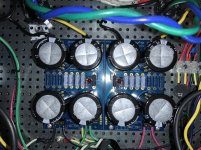
The wire is clear of the chassis floor. I was thinking I should add more links. I soldered connector terminals on the ST_IN2 and ST_IN3 side when I bridged that side. I wonder if those are acting like antennas. I’m removing them now.
What insulators are you using on your Mosfets?
I’m using these thermal interfaces from Mouser. One layer under each mosfet and they are a little larger than the mosfet on all sides, so the mosftes fit completely on top of them.
CD-02-05-247-2 Wakefield-Vette | Mouser
how about these?Can you take some more photos? Well-lit and in-focus, as always.
Attachments
-
 C9A46112-F53D-48A0-B4F1-E7532EA76FFE.jpeg482.7 KB · Views: 250
 -
 52B407F4-61CB-4F3D-A5F5-03CCE75E7452.jpeg404.1 KB · Views: 243
 -
 BB4F5043-1E56-4173-8756-DE77C6A1032D.jpeg406.7 KB · Views: 240
 -
 0A9B5CDE-C322-49A0-9B85-20F9420E2D28.jpeg343.8 KB · Views: 239
 -
 CCEB25DA-3DB2-4664-811B-3CF299A2AD97.jpeg382.9 KB · Views: 233
 -
 39064191-09AB-49E8-BB60-335BD0B35C0B.jpeg339.1 KB · Views: 128
 -
 0772492F-82FB-436D-ADAF-351B7CE34487.jpeg283.4 KB · Views: 134
Last edited:
It's a long shot, but it couldn't hurt to see if any of your input wires may be touching the heatsink. I didn't clip the lead properly on the backside of the amp board in one of my builds, and it was making contact. Gave me fits until I found it.
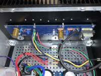
Edited to add - are your inputs wired in reverse on at least one channel? Right side, but white input jack. Looks like the jacketed wire is running to pos input on the back panel, but to gnd on the board? Can't tell perfectly from the pic, and I'm doing it off memory from the boards. Just give it a look see. (Ingore that... I zoomed in on the pic)...
Edited to add - are your inputs wired in reverse on at least one channel? Right side, but white input jack. Looks like the jacketed wire is running to pos input on the back panel, but to gnd on the board? Can't tell perfectly from the pic, and I'm doing it off memory from the boards. Just give it a look see. (Ingore that... I zoomed in on the pic)...
Last edited:
Haven't read everything.
Have you tried putting all your ground wires into the same screw down terminal?
How about trying a single monoblock configuration and see if you can get one channel operating without hum on the output.
It's always a good idea to solder ground wires to the boards, do that also.
Have you tried putting all your ground wires into the same screw down terminal?
How about trying a single monoblock configuration and see if you can get one channel operating without hum on the output.
It's always a good idea to solder ground wires to the boards, do that also.
It's a long shot, but it couldn't hurt to see if any of your input wires may be touching the heatsink. I didn't clip the lead properly on the backside of the amp board in one of my builds, and it was making contact. Gave me fits until I found it.
Edited to add - are your inputs wired in reverse on at least one channel? Right side, but white input jack. Looks like the jacketed wire is running to pos input on the back panel, but to gnd on the board? Can't tell perfectly from the pic, and I'm doing it off memory from the boards. Just give it a look see. (Ingore that... I zoomed in on the pic)...
I checked the input wires again and they’re on the right way. I have also checked clearances under the boards and nothing is close to touching the heatsinks. In fact I did that check before I turned the amp on for the first time.
Thanks for your suggestions!
It's a long shot, but it couldn't hurt to see if any of your input wires may be touching the heatsink. I didn't clip the lead properly on the backside of the amp board in one of my builds, and it was making contact. Gave me fits until I found it.
Edited to add - are your inputs wired in reverse on at least one channel? Right side, but white input jack. Looks like the jacketed wire is running to pos input on the back panel, but to gnd on the board? Can't tell perfectly from the pic, and I'm doing it off memory from the boards. Just give it a look see. (Ingore that... I zoomed in on the pic)...
Haven't read everything.
Have you tried putting all your ground wires into the same screw down terminal?
How about trying a single monoblock configuration and see if you can get one channel operating without hum on the output.
It's always a good idea to solder ground wires to the boards, do that also.
I have another transformer with a steel cover coming tomorrow. If replacing the transformer and shielding it from the rest of the amp behind steel doesn’t eliminate the hum, I’m going to pull all the boards out to go through every component, solder joint and connection.
Shielding can help a lot. Consider mu metal shielding of the input transformers on the board.
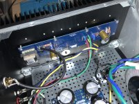
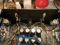
I would also look to further separate the input, and output wires from all the AC lines. One of your output wires looks to be draped on the terminal block. That could be a perspective issue with the photo though.
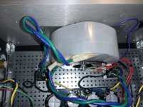
Consider twisting all your AC wires, in +/- pairs. The wires from terminal blocks to power transformer are all untwisted, asking for hum.
Also, be aware that the CL-60s get HOT, best not let them be touching any other wires.
I would also look to further separate the input, and output wires from all the AC lines. One of your output wires looks to be draped on the terminal block. That could be a perspective issue with the photo though.
Consider twisting all your AC wires, in +/- pairs. The wires from terminal blocks to power transformer are all untwisted, asking for hum.
Also, be aware that the CL-60s get HOT, best not let them be touching any other wires.
Last edited:
If the new transformer doesn't fix the problem, then please solder all ground conections.
You want the impedance to be as low as possible even if it weren't a problem now, as oxides form the contact resistance will continue to rise to the point of having a very noisy ground connection.
Soldering will eliminate this problem as the joint interface is completely encapsulated.
You want the impedance to be as low as possible even if it weren't a problem now, as oxides form the contact resistance will continue to rise to the point of having a very noisy ground connection.
Soldering will eliminate this problem as the joint interface is completely encapsulated.
I've got the humming blues too...
I'm currently testing my VFet v1 and have the dreaded hum blues. Wiring and ground loops don't appear to be the issue as having one channel out of the chassis (about 12" away from the toroidal transformer) gets me down to 0.6mV AC. But as soon as a move the board closer - I can see the mV AC going up to as high as 10mV at a distance of 6" away.
One option as others have mentioned is to build shields over the input transformer. Another is to go entirely external power supply. Such a pity as usually the limiting factor in choosing a chassis is the size of the heatsink required. But instead, when you add in the input transformer, it's more like how far it can be inside the chassis.
I have another transformer with a steel cover coming tomorrow. If replacing the transformer and shielding it from the rest of the amp behind steel doesn’t eliminate the hum, I’m going to pull all the boards out to go through every component, solder joint and connection.
I'm currently testing my VFet v1 and have the dreaded hum blues. Wiring and ground loops don't appear to be the issue as having one channel out of the chassis (about 12" away from the toroidal transformer) gets me down to 0.6mV AC. But as soon as a move the board closer - I can see the mV AC going up to as high as 10mV at a distance of 6" away.
One option as others have mentioned is to build shields over the input transformer. Another is to go entirely external power supply. Such a pity as usually the limiting factor in choosing a chassis is the size of the heatsink required. But instead, when you add in the input transformer, it's more like how far it can be inside the chassis.
Last edited:
Shielding can help a lot. Consider mu metal shielding of the input transformers on the board.
I would also look to further separate the input, and output wires from all the AC lines. One of your output wires looks to be draped on the terminal block. That could be a perspective issue with the photo though.
Consider twisting all your AC wires, in +/- pairs. The wires from terminal blocks to power transformer are all untwisted, asking for hum.
Also, be aware that the CL-60s get HOT, best not let them be touching any other wires.
Great tips, thank you!
If the new transformer doesn't fix the problem, then please solder all ground conections.
You want the impedance to be as low as possible even if it weren't a problem now, as oxides form the contact resistance will continue to rise to the point of having a very noisy ground connection.
Soldering will eliminate this problem as the joint interface is completely encapsulated.
Yes, this makes sense. I did take precautions such as using flux to solder the terminal connectors to the wire, but I do understand that the best connection would be to solder the wires to the board. It has been convenient to have these connectors to troubleshoot and I think once I get the amp to be quiet I will go with this more permanent solution as you suggest. Thanks!
I'm currently testing my VFet v1 and have the dreaded hum blues. Wiring and ground loops don't appear to be the issue as having one channel out of the chassis (about 12" away from the toroidal transformer) gets me down to 0.6mV AC. But as soon as a move the board closer - I can see the mV AC going up to as high as 10mV at a distance of 6" away.
One option as others have mentioned is to build shields over the input transformer. Another is to go entirely external power supply. Such a pity as usually the limiting factor in choosing a chassis is the size of the heatsink required. But instead, when you add in the input transformer, it's more like how far it can be inside the chassis.
I am going to look into mu metal shields for the input transformers. I used the same 4u chassis many others here use, so it is interesting that hum complaints are few and far between here.
I built power humpties for my Gain Clones, ala 47 Labs and those run extremely quiet. Nobody was configuring their F6 that way so I didn’t think I would need to think about doing that. If I build another F6 I will consider splitting the power supply into its own chassis.
Thanks!
Nicely assembled Layout.
Curious results tho My F6 generates Zero noises.. Ears pressed tight to the dustcaps of My tannoys.
Volume at max or min. No noises at all.. exactly same as when unplugged from the mains.
I assumed this was as it should be, typical of the F6. Surprised to read it may not be.
Only difference I can tell (from pix) is that My Antek is mounted flat onto my diy ali cases' ali bed plate.. Not a perforated tin thing.
Ohh no fender washers on the 240s either.. Not as if mine get much past warm.
Last edited:
Nicely assembled Layout.
Curious results tho My F6 generates Zero noises.. Ears pressed tight to the dustcaps of My tannoys.
Volume at max or min. No noises at all.. exactly same as when unplugged from the mains.
I assumed this was as it should be, typical of the F6. Surprised to read it may not be.
Only difference I can tell (from pix) is that My Antek is mounted flat onto my diy ali cases' ali bed plate.. Not a perforated tin thing.
Ohh no fender washers on the 240s either.. Not as if mine get much past warm.
Thanks for affirmation of my layout. I was surprised to hear that hum when I fired mine up. It’s not audible when playing music, but I have to think it colors the sound in some way.
I don’t think the perforated platform has anything to do with this, but now I wonder if those fender washers do. I have touched those washers to see if the hum changed, but it didn’t. However, removing them is another thing I can try if the new transformer doesn’t solve the problem.
Thanks!
If the new transformer doesn't fix it and you can't find a dc blocker build this.
Changing the transformer didn't solve the problem - I still have the buzzing/humming noise in my speakers.
I found another issue and fixed it too, but this didn't solve the buzzing/humming noise either. I found that R9 and R10 in the PSU were 2.2K wirewound 3W resistors so I swapped them out for 22K metal film 3W resistors, but as I said the buzzing/humming is still there I was so hopeful with this change! Oh well...
Thanks for the DC filter schematic. I am reading about it on the ESP website. All they really say about this circuit is that it may prevent a large, 500va or bigger transformer itself from "growling". Unless I missed this (and that is possible) the article doesn't really indicate that the DC offset issue they describe causes a problem in the transformer output, or that the circuit shown will mitigate issues with buzzing or humming in an audio circuit being driving by the PSU a transformer is attached to.
Note that I have adjusted DC Offset at the speaker connectors to effectively zero. Please help me understand then why DC offset in the mains would show up in my speakers.
One last thing. Could the noise I'm hearing be caused by the LEDs in the PSU, or by the resistors I used to reduce voltage to them? How about the LEDs in the amp boards? Could they be making the noise audible in my speakers?
Thanks!
If the magnetic flux becomes saturated because of DC, it will cause a whole host of problems.
If the new transformer is also buzzing you will want to fix this, you will never get a good result with a transformer performing like this.
Disconnect the amp and test psu with light bulb tester
Measure Rail Voltages
Measure Resistance from Signal 0V to chassis
Does Transformer still buzz
If all that checks out, connect one channel and retest
Disconnect that channel then connect the other channel and test
How about the LEDs in the amp boards? Could they be making the noise audible in my speakers?
Thanks!
What will cause noise, is if your references used to bias your circuit are current starved.
What resistance value are you using to feed the zener/led references?
- Home
- Amplifiers
- Pass Labs
- F6 Illustrated Build Guide