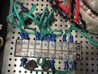
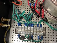
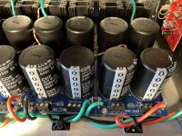
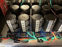
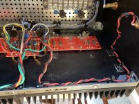
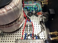
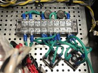
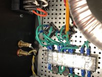
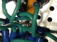
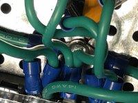
Good morning guys, I got up and made the wiring changes inside the F5T adding another lifting bridge and CL60. I still have the slight 60hz hum in the right channel. Left channel, totally silent. I’ve included some more pics.
Attachments
-
 C5B12633-8776-40EF-B7C3-2C312DEEB760.jpg1 MB · Views: 138
 -
 99EFC549-52F4-4B7C-9E9E-7FBFCC540BB7.jpg1 MB · Views: 136
 -
 91F55FC4-B7F1-43F1-9CD4-FCB8DB7F3E48.jpg1 MB · Views: 133
 -
 0E1C793B-63A4-41CC-A1A0-8AA0FEFFF073.jpg1 MB · Views: 132
 -
 19C7A225-CDB6-44C9-9F62-32F375DAF0E1.jpg1,016.6 KB · Views: 126
 -
 F5A16716-E1EC-4457-80F1-3A42B1AA0472.jpg1,008.5 KB · Views: 75
 -
 C1E4CCF1-C07D-4C0C-A7D5-17FF18BCD0DE.jpg902.3 KB · Views: 67
 -
 0EBF340C-329B-483D-8521-5954DC1B890A.jpg909.7 KB · Views: 60
 -
 A9174EC6-D55B-489C-98DF-A78287E19669.jpg1 MB · Views: 63
Hi, Luvrockin!
Sad to hear the change made no difference. I kinda thought as much, given the tranny turning worked... any more headroom to turn the tranny even more?
Luckily there is always room for change! Lovely part about the hobby.
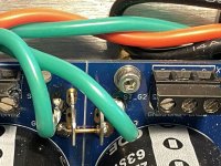
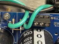
Yesterday I said something about differences between the two sides of the amp as a good place to start. I see that your AC connection block is very close to the right channel outputs. Ideally, of course, AC lines should run along the middle of the amp. That is often not possible.
Might I suggest you attempt moving the connection block a bit, or maybe trying to cover it with some metal that at the same time touches the chassis? The last suggestion is risky and might not work at all, but loosening some screws and cutting some zipties will be enough for this test. Intention here is to see if there is any difference at all in moving it away from the output or not.you can override the fuses to ease the test.
If this makes a difference, you might have a loop area somewhere picking it up. But we can get back to that.
Do also consider cutting the amp board gnd wire off the PSU, and connect it instead to different places out of the six spots in the euroblocks. If this make a difference, you might have a common impedance issue.
If turning the bias down reduces hum, it is indicative of the same issue. But important here is that it pertains only to one channel. That is the place to start.
Lastly: are there any other visible differences between the two amp halves? I am thinking the physical dimension here.
Cheers,
Andy
Sad to hear the change made no difference. I kinda thought as much, given the tranny turning worked... any more headroom to turn the tranny even more?
Luckily there is always room for change! Lovely part about the hobby.
Yesterday I said something about differences between the two sides of the amp as a good place to start. I see that your AC connection block is very close to the right channel outputs. Ideally, of course, AC lines should run along the middle of the amp. That is often not possible.
Might I suggest you attempt moving the connection block a bit, or maybe trying to cover it with some metal that at the same time touches the chassis? The last suggestion is risky and might not work at all, but loosening some screws and cutting some zipties will be enough for this test. Intention here is to see if there is any difference at all in moving it away from the output or not.you can override the fuses to ease the test.
If this makes a difference, you might have a loop area somewhere picking it up. But we can get back to that.
Do also consider cutting the amp board gnd wire off the PSU, and connect it instead to different places out of the six spots in the euroblocks. If this make a difference, you might have a common impedance issue.
If turning the bias down reduces hum, it is indicative of the same issue. But important here is that it pertains only to one channel. That is the place to start.
Lastly: are there any other visible differences between the two amp halves? I am thinking the physical dimension here.
Cheers,
Andy
Hmmm. Where is your chassis star ground? I can not from the pics see the point in the chassis where the IEC inlet/safety ground is attached to the chassis. If it is not, it is floating.
It should be connected straight to the chassis floor, not through a connection block.
Are my eyes deceiving me?
Have a beer, problem will be solved, stayer of the year.
Cheers,
Andy
It should be connected straight to the chassis floor, not through a connection block.
Are my eyes deceiving me?
Have a beer, problem will be solved, stayer of the year.
Cheers,
Andy
Last edited:
")

Dirk, very nice!! Andy, gonna give those a shot especially moving the block because that is right by the right channel. Possibly an excellent catch. If not I’ll go after the other suggestions. Also I’ve added a couple more pics. The star is under the whole pile of crapola, but it’s there. Check it out
Attachments
Question regarding my current F5 Turbo build. I originally built the unit with the most minimum powered parts:
- Antek 6224 - 32V Rails 600VA
- 80000uf 35V caps
- Non - cascode
- 5U enclosure
I am currently using the F5 turbo on a pair of Harbeth, but they just don’t sound as good as I would have hoped and they need more headroom. I am thinking about going with a 28V sec/800va transformer, 50V power caps, and then cascode the FE board. Is this worthy of an upgrade to get a higher bias and should I notice a considerable upgrade?
Thanks!
Question regarding my current F5 Turbo build. I originally built the unit with the most minimum powered parts:
- Antek 6224 - 32V Rails 600VA
- 80000uf 35V caps
- Non - cascode
- 5U enclosure
I am currently using the F5 turbo on a pair of Harbeth, but they just don’t sound as good as I would have hoped and they need more headroom. I am thinking about going with a 28V sec/800va transformer, 50V power caps, and then cascode the FE board. Is this worthy of an upgrade to get a higher bias and should I notice a considerable upgrade?
Thanks!
Wondering if anyone has done similar making changes to a minimum spec F5 turbo then making adjustments.
When building the F5T as dual mono, does each side need its own star ground or should they all meet at one common point. Still got this slight hum in the right channel. Pulled all the wires off both sides of the psu’s and connected noisy channel to quiet side psu including the ground. The noise followed. Tried circuit with separate ground lifts with thermistors, then ground lift on quiet channel and just thermistor to ground on noisy channel with no difference, moved the terminal strip more towards center of the amp, no difference. Any thoughts?
Are you able to get the offset below 15mV? It seems a little high from what we've seen most builds averaging.
Also if possible, check whether the offset is DC or AC (you'll need to switch your meter to AC range - it should read 0 or much lower than the 15mV you're getting). You might have some 60Hz leaking through the amp, if it's not a ground loop.
One cure that works on occasion is to connect the two channel grounds together with a very thick wire from one PCB to the other. If you have a dual mono setup, each needs its own 'loop breaker', if you're installing them.
Inputs shorted or connected to source?
Thank you guys, Yes Dennis Hui, you are correct. Sangram it is the left channel burned up but is dead silent and the right channel I had no issues with except the slight hum.
Hi, Rockin! Sorry to hear that, but also informative with locating the source.
Just a quick one: have you tried swapping PSUs between channels? Iow, disconnecting and putting the left psu to the right amp boards and vice versa?
That would help isolate the error further. Also, try putting your hand on the tranny and applying some pressure, and or tighten it down a bit more, just to see if it makes a difference and whether the hum is mechanical or caused by something else. Sangram AC offset test is very good. I’d follow his advice, always.
Also, you mentioned increased hum when moving amp gnd wire away from 0v junction. This is a little bit strange, but might maybe enlighten some of the smarties in here in finsing the issue.
I wiuld also try putting a wire with quickcons across the blades at the junction, just to see what less impedance between gnd plane halves do for you.
PS: to check if your chassis is floating, try turning on without a source and UNSHORTED inputs. Note the hum level. Then short input and compare. If the hum is louder with unshorted inputs, much louder, chassis might be floating. But it can be other things as well, but this test might help finding the fault =)
Last edited:
is it okay to proceed here?
Just wanted to check if this was normal: 1/2 volt across speaker OUT.
I think I'm supposed to be getting about nothing (in the mV range) over the speaker outputs +/- ??
As I dialed up the variac, to 44V, one channel at a time. On both channels (separately) I was getting a half volt on the output,
R-channel
44V variac, 1.431VDC on PSU out, 0.495V across speaker out +/-, bulb glowing
L-channel
44V variac, 1.435VDC on PSU out, 0.493V across speaker out +/-, bulb glowing
Input RCAs are not shorted. Nothing is hooked up to speaker terminals, except the multi-meter. I dialed P1 and P2 as close to zero as they'd go, which was around 1.1ohm (across TP1-2 and TP3-4 on FE board).
Do I have a short? Am I measuring something incorrectly? I'm glad the boards had the same numbers - I wired them the same, even if incorrect somewhere.
In 6L6 procedure, he mentions "Place voltmeters across TP of output board, one on N-channel, one on P channel." What exactly is the TP of output put board? There's a TP1, 2, and 3.
Mr. Drewk, I am not sure I am the right person to help here, but I am sorry your previous post was not answered.
Whatever the test point, screw them and place your DMM’s across your source resistors instead. Post readings here to the corresponding output readings, and Sangram and Dennis will be able to decipher what it means.
Also, be sure to short your inputs if you haven’t allready.
You might be supposed to read around zero, but you might not have a problem at all. Measure the source resistors, and take it from there. There might be some current across them (voltage loss), but it is not nescessarily something to worry about. You just don’t want them running wild with the pots turned all the way down.
Remember, what turns out at the outputs is amplified by the gain of the amp (20db+), so it does not take very much to get you to 500mVdc at the outputs.
Edit: That DC measured?
Try turning (P2?) a wee bit and see if the number changes. If you are able to zero, I’d say your good to start slowly biasing up. Please wait for someone more experienced than me to chime in first, it is a moody amp and I am not exactly Choky, Dennis, Sangram, 6L6 or the likes.
Good luck!
Andy
Last edited:
- Home
- Amplifiers
- Pass Labs
- F5Turbo Illustrated Build Guide