Monsieur Drewk,
I'm not familiar with F5T or the PCB set but I will suggest the following:
1) Power off and short the inputs.
2) Measure the resistance across R5 and R6. They should be close to zero. If not,
adjust P1 and P2 until they are.
3) Power up again.
4) Check DC offset.
5) Check voltages across R5 and R6.
6) check voltages across source resistors R17, R21. They should tell you about current going through the P and N half of the output stage.
Let's see what you get.
Are you able to get the offset below 15mV? It seems a little high from what we've seen most builds averaging.
Also if possible, check whether the offset is DC or AC (you'll need to switch your meter to AC range - it should read 0 or much lower than the 15mV you're getting). You might have some 60Hz leaking through the amp, if it's not a ground loop.
One cure that works on occasion is to connect the two channel grounds together with a very thick wire from one PCB to the other. If you have a dual mono setup, each needs its own 'loop breaker', if you're installing them.
Inputs shorted or connected to source?
Sangram and anyone who cares to join in,
I’m sorry about not getting back sooner, it was a rough day. I have some info and questions. So my offset AND bias are starting to really frustrate me. My bias seems to constantly change affecting offset. The 15mv you mentioned was originally set at a + 1-2mv but as the amp runs, the bias tends to go up affecting offset. So I had the bias set at 375mv with offset at about -1-2mv, pretty much on both channels give it take minimally. Today I turn the F5T on with (6) dmm’s connected, (3) to each channel so I could watch. At start up, the bias shout up to about 400mv on both channels and the offset was -89mv+/-. As the F5T heated up, after about an hour, the bias started to drop down to about 375ish mv where I had it set but the bias hung around -34/-35. I left it on to observe and after another hour, the bias was up to 400mv and the offset was at 0-1mv. The sinks were quite warm at about 58*C. So I went through the motions again and reset bias and offset again. This isn’t the first time the bias and offset doesn’t hold. As for my, hum I tried connecting the ground as you suggested but but made no difference. Lastly, the inputs are shorted.
Andy, yes I swapped the power supply wiring totally including the ground lifters but made no difference. I also tried before unsoldering everything was moving the ground as you suggested but for whatever reason the hum got worse. I also moved that power block away from that side. With my wife’s ear in the speaker, it made no difference.
The question I have is is the F5T and unstable amp? I know it’s not a beginner project but I’m in it, approaching the finish line, with the conversation about the diodes side say use, some don’t and now this bias/offset thing, it’s got me wondering if I should scrap the idea of the F5T and go towards something not as finicky? Thoughts
hello. The small thermistors on the output boards, do they have good contact with the outputfets? this devices sense heat and compensate bias accordingly.
Is the bias drift in one or both channels? Is it both N-ch and P-ch, or only one of them.
Is the bias drift in one or both channels? Is it both N-ch and P-ch, or only one of them.
Sangram and anyone who cares to join in,
I’m sorry about not getting back sooner, it was a rough day. I have some info and questions. So my offset AND bias are starting to really frustrate me. My bias seems to constantly change affecting offset. The 15mv you mentioned was originally set at a + 1-2mv but as the amp runs, the bias tends to go up affecting offset. So I had the bias set at 375mv with offset at about -1-2mv, pretty much on both channels give it take minimally. Today I turn the F5T on with (6) dmm’s connected, (3) to each channel so I could watch. At start up, the bias shout up to about 400mv on both channels and the offset was -89mv+/-. As the F5T heated up, after about an hour, the bias started to drop down to about 375ish mv where I had it set but the bias hung around -34/-35. I left it on to observe and after another hour, the bias was up to 400mv and the offset was at 0-1mv. The sinks were quite warm at about 58*C. So I went through the motions again and reset bias and offset again. This isn’t the first time the bias and offset doesn’t hold. As for my, hum I tried connecting the ground as you suggested but but made no difference. Lastly, the inputs are shorted.
Andy, yes I swapped the power supply wiring totally including the ground lifters but made no difference. I also tried before unsoldering everything was moving the ground as you suggested but for whatever reason the hum got worse. I also moved that power block away from that side. With my wife’s ear in the speaker, it made no difference.
The question I have is is the F5T and unstable amp? I know it’s not a beginner project but I’m in it, approaching the finish line, with the conversation about the diodes side say use, some don’t and now this bias/offset thing, it’s got me wondering if I should scrap the idea of the F5T and go towards something not as finicky? Thoughts
I would not give up just yet. Though I believe you will be well pleased with a BA-3 with 24v rails, you have come too far to throw in the towel, imho.
Just to see if I understand you correctly: You swapped PSUs, but the hum was still in the same channel? The answer is really important.
Regards,
Andreas
Andy, thank you for jumping in. Yes exactly. I removed the wires from both of the psu’s. I connected the right channel (humming channel) amp to the left channel psu. I also used the left channel ground and lifter.
I would check the contact between thermistors and the MOSFETs, which are the prime reason for large differences in bias set points. Also when the coupling is too intimate, you'll notice quite a bit of movement as the amp warms up. If you couple the thermistor to the heatsink, for example, you'll have a much more steady and predictable bias and offset but a very long warm-up time and a very large difference between cold and hot amp because the heatsink take very long to warm up.
What's important to check is the offset itself, and whether it is AC or DC. Often a DC measurement will reveal an AC component, which should be below 1mV for zero noise in most any speaker.
In general the F5T is not an unstable design. The thermal behaviour is a direct consequence of the attempt to keep things simple and the component count as low as possible. I do have a basic disagreement with the thermistor arrangement in the Turbo, so I use one that is closer to the original F5 layout.
Per se your bigger issue is the hum, which you should not have with the inputs shorted. I wouldn't worry about bias and offset at this stage.
hello. The small thermistors on the output boards, do they have good contact with the outputfets? this devices sense heat and compensate bias accordingly.
Is the bias drift in one or both channels? Is it both N-ch and P-ch, or only one of them.
Audiosan thank you for the input. I saw in a previous post in this thread I believe between Allinmyhead Patrick and Dennis Hui about the use of thermistors with a eyehole to fasten it. Since I was already having this drifting issue, I thought I’d give those a shot. They helped a bit but my bias is still all over the board. It’s pretty much in both channels although the right is much worse and in both P & N
boards. Last night before I hit the sack, I shut down the amp with the bias set at 370mv with dc almost 0 on both channels. I am going to work now and will turn it on again tonight and I’ll let you guys know what it does at start up and after it’s at operating temp.
I would check the contact between thermistors and the MOSFETs, which are the prime reason for large differences in bias set points. Also when the coupling is too intimate, you'll notice quite a bit of movement as the amp warms up. If you couple the thermistor to the heatsink, for example, you'll have a much more steady and predictable bias and offset but a very long warm-up time and a very large difference between cold and hot amp because the heatsink take very long to warm up.
What's important to check is the offset itself, and whether it is AC or DC. Often a DC measurement will reveal an AC component, which should be below 1mV for zero noise in most any speaker.
In general the F5T is not an unstable design. The thermal behaviour is a direct consequence of the attempt to keep things simple and the component count as low as possible. I do have a basic disagreement with the thermistor arrangement in the Turbo, so I use one that is closer to the original F5 layout.
Per se your bigger issue is the hum, which you should not have with the inputs shorted. I wouldn't worry about bias and offset at this stage.
Sangram, Athank you for your input as well. This post just came in as I was responding to Audiosan. I am actually using fasten down thermistors. These helped a bit but it’s still all over the place. I checked my offset with the meter set to dc but did check it when set on AC as well when I turned it on
last night after about an hour. Although the bias had come down to where it was set originally, the offset was -34/-35ish. I checked with the meter set to AC and I had +4.7VAC on the right channel and +3.8VAC on the left channel with the inputs shorted and no speakers attached.
It then does not look to be a ripple issue. I would doble check that the bottom tranny is not naked (bare metal) underneath, also that no prt of you psu boards are conducting to chassis. Perhaps try measuring voltages between chassis and an external grounding point.
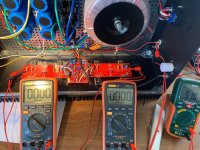
Your wavering bias probably explain the blowups. I kinda thought there might be an underlying problem. Are you sure your MOSFETs are not installed backwards? One one of the pics it looks like the fets are UNDER your boards. Or is that just the old diode placement?
Andy
Your wavering bias probably explain the blowups. I kinda thought there might be an underlying problem. Are you sure your MOSFETs are not installed backwards? One one of the pics it looks like the fets are UNDER your boards. Or is that just the old diode placement?
Andy
What's important to check is the offset itself, and whether it is AC or DC. Often a DC measurement will reveal an AC component, which should be below 1mV for zero noise in most any speaker.
I checked with the meter set to AC and I had +4.7VAC on the right channel and +3.8VAC on the left channel with the inputs shorted and no speakers attached.
Are you sure?
???? Well, I agree. That would be a bit more than a "ripple".It then does not look to be a ripple issue.
luvrockin, please verify your measurements (and scales). Even 3.8mV AC noise
will be quite noticeable.
BTW, was the lid on the amp during your bias/DC monitoring process?
will be quite noticeable.
BTW, was the lid on the amp during your bias/DC monitoring process?
I know. I should have put one of these little guys 😉 to convey the understanding. If PSU ripple (particularly on one channel's PSU) were the issue, the hum would have followed the PSU as was your intent. Mine was to make a (clearly bad) joke that ~4VAC on the outputs with the inputs shorted was a bit more than "ripple". Apologies. I should have been more clear.
Either way, if that measurement is accurate (I am not sure it is), then I am very glad that luvrockin did not hook up a pair of earbuds for noise diagnosis. Poof. Also, if there was actually ~4VAC on the outputs, then it would be MUCH more than a hum with loudspeakers.
I hope that makes a bit more sense.

Edited to add - Dennis snuck in a post between. 😀 Agreed, Dennis. That measurement is likely incorrect. Also agreed that even if it's ~4mVAC that it could be noticeable. However, the 0.9mVAC (~20%) difference between left and right channel wouldn't seem to be a big enough delta to have one channel "quiet" while the other hums. I'd think both would hum.
Either way, if that measurement is accurate (I am not sure it is), then I am very glad that luvrockin did not hook up a pair of earbuds for noise diagnosis. Poof. Also, if there was actually ~4VAC on the outputs, then it would be MUCH more than a hum with loudspeakers.
I hope that makes a bit more sense.
Edited to add - Dennis snuck in a post between. 😀 Agreed, Dennis. That measurement is likely incorrect. Also agreed that even if it's ~4mVAC that it could be noticeable. However, the 0.9mVAC (~20%) difference between left and right channel wouldn't seem to be a big enough delta to have one channel "quiet" while the other hums. I'd think both would hum.
Last edited:
No worries dude, I stand corrected to you anytime. Sorry for the short answer, was April beachin’ with the family. Tried swimming, a tad cold. Better and warmer stuffing my WLS after.
Also Luvrockin, did some easy fast math on my calc. I’d not exceed 350-360mv drops over source resistors wrt bias, given what the 5U can disspate. Given you have 36,5v rails. In the current situation. Until you find the issues with the help of Dennis and the other Greedy Boyz, I suggest you take it down even further.
Regards,
Andy
Regards,
Andy
 I just love the auto-correct feature in today’s days and age is all devices. It’s 4.7mvac and 3.7mvac
Pretty sure "source resistors" are R5 and R6. I checked them:place your DMM’s across your source resistors instead.
R5 0.4Ω
R6 0.3Ω
I cut off an old RCA cord, and twisted core with shield: shorted. Plugged one each into the Input, shorting signal to ground.Also, be sure to short your inputs if you haven’t allready.
Thank you @andynor!
done. (see above: RCA shorted signal to ground)1) Power off and short the inputs.
Done. Got R5 0.4Ω, and R6 0.3Ω.2) Measure the resistance across R5 and R6. They should be close to zero. If not, adjust P1 and P2 until they are.
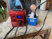
I didn't go to the full 119VAC. My dim-bulb was glowing, and I want to be sure it's safe to dial up voltage on variac.3) Power up again.
Still a bit nervous here, I dialed variac to: 57VAC, bulb glowing, 2.97VDC ST_V+ to ST_V-4) Check DC offset.
5) Check voltages across R5 and R6.
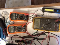
DC Offset (measured at speaker outs) 0.51VDC
R5 and R6 0.000VDC
At the same variac settings above, both R17 and R21 0.000VDC. Which I think is what we want when P1 and P2 are turned all the way down to 1.2Ω each (as low as they'll go at the 'click')6) check voltages across source resistors R17, R21. They should tell you about current going through the P and N half of the output stage.
relevant pics Shared album - Drew Kerlee - Google Photos
Attachments
luvrockin, please verify your measurements (and scales). Even 3.8mV AC noise
will be quite noticeable.
BTW, was the lid on the amp during your bias/DC monitoring process?
Dennis, yes the lid was on with the inputs shorted, no speaker or load connected to outputs.
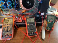
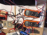
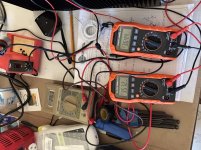
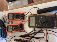
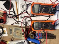
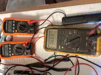
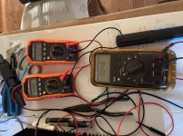
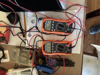
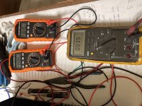
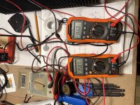
I wanted to share the info you maybe this helps explain my bias/offset situation. I’ve taken pics from the time I turned the amp on and every 15 minutes up to 3hrs. I uploaded the initial and some random in between. I documented the others for review. The (2) orange meters with the yellow Fluke meter is my right channel and the other (2) orange with the beige meter is my left channel. The yellow Fluke and beige Thermal are reading offset and the orange are bias.
Start up
Right bias- 410/388mv offset -114.3mv
Left bias- 395/386 offset -92.1
15 mins
Right- bias 360/338.9 offset -60.3
Left- bias 357.1/350.3 offset -63.7
30 mins
Right- bias 369.9/347.5 offset -51
Left- bias 360.6/353.7 offset -45.4
45 mins
Right- bias 376/353.9 offset -41.7
Left- bias 364.5/357.4 offset -34.1
1hr
Right- bias 383.3/360.9 offset -40.1
Left- bias 367.5/360.3 offset -25.7
1hr 15 mins
Right- bias 370.8/349.1 offset -22.6
Left- bias 364.4/357.2 offset -26.3
1hr 30mins
Right- bias 364.5/343.2 offset -8.3
Left- bias 363.8/356.7 offset -19.3
2hr
Right- bias 365.2/344 offset -4.8
Left- bias 364.2/357 offset -18.5
3hrs and I adjusted left channel @ 2.5hr
Right- 364.5/343.4 offset 3.5
Left- 366/358.7 offset 2.2
Any thoughts?
Attachments
-
 51FFFEF8-A5C9-482F-8CEE-4681382548A8.jpeg405.5 KB · Views: 191
 -
 782232A4-8A18-4F2D-B298-A35F542D5F35.jpeg451.5 KB · Views: 176
 -
 74CA6BC4-8954-48E5-BAC4-BE9CA4C350F1.jpeg409.5 KB · Views: 64
 -
 0AE1194F-1EEE-4DE3-8E4F-6201F2785A47.jpeg346.5 KB · Views: 71
 -
 F7E01D84-D1C8-41A9-9FDA-C60497BAD225.jpeg439.3 KB · Views: 68
 -
 54795FFD-8F67-40C3-AB6D-1F2E9ED4EC18.jpeg407.1 KB · Views: 79
 -
 27271374-FBCC-4C89-B8A0-DD8E93F32E57.jpeg341.8 KB · Views: 70
 -
 D45988DF-0C2E-460F-BEE6-D130C9EBF89C.jpeg477.6 KB · Views: 71
 -
 8D805492-448A-4AC6-90CF-73B9E188BB31.jpeg588.4 KB · Views: 72
 -
 001DEF0B-73E2-4691-BE58-AEBF398384C5.jpeg558.1 KB · Views: 72
Thermal equilibrium takes a long time to occur, it's a big chassis and everything needs to get to final temperature.
This is completely normal.
This is completely normal.
- Home
- Amplifiers
- Pass Labs
- F5Turbo Illustrated Build Guide