luvrockin, like 6L6 I don't see any issues with your bias and offset. It seems completely normal.
The bigger the heatsink, the longer the warm-up and drift.
How is the hum now?
The bigger the heatsink, the longer the warm-up and drift.
How is the hum now?
Still a bit nervous here, I dialed variac to: 57VAC, bulb glowing, 2.97VDC ST_V+ to ST_V-
DC Offset (measured at speaker outs) 0.51VDC
R5 and R6 0.000VDC
So you have the variac at 57VAC (about 1/2 AC voltage) and you have less
than 3V DC between V- and V+ on the PS board (so about 1.5V between
V- and GND, and 1.5V between GND and V+)? Am I understanding
that correctly? If so, and assuming there's been enough time for the caps to
charge up, it does seem there's a short somewhere.
Is this with both boards channels attached?
I think I saw a photo showing in your album showing about +/-34V on the
PS. Can you confirm if the bulb tester was in place for that measurement and that the variac was at 119VAC? If a bulb tester was used, did the bulb glow and then dimmed?
luvrockin, like 6L6 I don't see any issues with your bias and offset. It seems completely normal.
The bigger the heatsink, the longer the warm-up and drift.
How is the hum now?
Thank all you guys for this info. I was mainly concerned about when I turn the amp on and my bias is over 400mv and the offset is -110 & -92. I don’t know at what voltage I could start damaging my speakers.
Sangram, although minimal, I still have the hum. I moved them ground, sanded my points of contact and connections with no difference. I bought some shielded cable for the inputs. When that arrives, I’ll give it a shot. This weekend I’m going to totally move the transformers away from the right side as an experiment.
Andynor, I checked the bottom of the transformers and there is a rubber boot isolating the transformer from the chassis. Moving the transformers will also allow me to move the terminal block even further away from the right channel. Im thinking this will at least tell me if it’s a wiring issue or magnetic issue.
If we assume an offset of 1V in order to exaggerate the situation, the speaker will be dissipating around 1/8 of a watt (for an 8 ohm speaker). This should not be a problem for almost any speaker. A 1.5V AA battery, for example, is used on regular basis to test speaker polarity when the manufacturer doesn't mark the polarity.
At 100mV, I wouldn't worry.
Back to your hum.
If you have hum in the PCB (confirmed by swapping power supply leads between channels and with input shorted) it's probably a dry solder, loose contact or questionable component around the JFET inputs. Unfortunately I'm not familiar with the store PCBs so I can be of limited help.
I would definitely use shielded wire for the inputs. What you've got going there is not suitable at all (I know that's counter to many opinions). Typically the shortest path to ground is how the current will flow, so using a very thin wire for the inputs is usually recommended so that power supply currents don't flow through thick input ground leads. I usually had good luck lifting the shield at one end (in a 2C+S wire), but that's a bit outside the scope of this discussion.
Sangram, thank you for the suggestions and piece of mind. I was thinking I could be frying my speakers if connected. You also gave me something else to look for now that you mentioned the solder joints around the jfets. I did replace them and I will double check them to be sure. I’m optimistic about the shielded cable as well.
100mV dc offset is not a concern, especially since it drops as the amp warms up.
The Aleph amps, for example, specs a DC offset of <100mV.
Please check for connections and reflow joints as suggested by Sangram. Also
you might see if there are excess flux residuals that you should clean off.
The Aleph amps, for example, specs a DC offset of <100mV.
Please check for connections and reflow joints as suggested by Sangram. Also
you might see if there are excess flux residuals that you should clean off.
to MrDrewk #1039 / #1057
Hello MrDrewk,
at your first start-up you should have a very low (close to 0V) DC-offset at
your speakeroutputs. Your value (close to 0.5V) is definitively too high.
Your DMMs are connected correctly over the bias resistors (as I could see it on your pics). One DMM over one bias resistor (N-channel), one DMM over one bias resistor (P-channel).
You could also use the TP2 and TP3 on the outputboards (which are directly connected to one of the bias resistors). So, it doesn#t matter if you clip your DMM-probes to TP2/3 or directly to the legs of one of the bias resistors. You will get the same readings.
The big question is: Where does your large DC-offset at speakeroutput comes from although your amp isn't biased up??? 😕
Did you use the dimbulbtester to check the PSU alone (without the frontendboard + outputboards connected) for faults?
Have you checked your voltages out of your PSU before you connected your amp-boards? What have been the values? +voltage referenced to ground and -voltage referenced to ground.
As long as the dimbulbtester doesn't dim down/goes off - there is something wrong.
I would disconnect my amp boards from the PSU and would check the PSU-voltages first. With focus on their symmetry (+Vout PSU = -Vout PSU).
Greets
Dirk 😀
p.s.: it can take some time till I answer - I am most often busy with projects/job
I can't hang the hole day on the computer - so please, be patient with me
to MrDrewk
Hello MrDrewk,
is your pot3 (200 Ohm-pot) on the frontendboard adjusted to mid-position?
Greets
Dirk
Hello MrDrewk,
is your pot3 (200 Ohm-pot) on the frontendboard adjusted to mid-position?
Greets
Dirk
With both boards disconnected, variac at 57VAC, dim-bulb stays dark whole time.So you have the variac at 57VAC (about 1/2 AC voltage) and you have less
than 3V DC between V- and V+ on the PS board (so about 1.5V between
V- and GND, and 1.5V between GND and V+)? Am I understanding
that correctly? If so, and assuming there's been enough time for the caps to
charge up, it does seem there's a short somewhere.
gnd > ST_V- -16.54VDC
gnd > ST_V+ 16.60VDC
ST_V- > ST_V+ 33.0VDC
both boards are disconnected.Is this with both boards channels attached?
Dim-bulb tester has been inline the whole time. These were those readings:I think I saw a photo showing in your album showing about +/-34V on the
PS. Can you confirm if the bulb tester was in place for that measurement and that the variac was at 119VAC? If a bulb tester was used, did the bulb glow and then dimmed?
gnd > ST_V- -34.32VDC
gnd > ST_V+ 34.28VDC
Good question: just did. With neither FE boards attached, the dim-bulb was dark the whole time, even at full 120VDC.The big question is: Where does your large DC-offset at speakeroutput comes from although your amp isn't biased up??? 😕
Did you use the dimbulbtester to check the PSU alone (without the frontendboard + outputboards connected) for faults?
Also good question, here are a few numbers there:Have you checked your voltages out of your PSU before you connected your amp-boards? What have been the values? +voltage referenced to ground and -voltage referenced to ground.
variac at 120VAC
gnd > ST_V- -34.32VDC
gnd > ST_V+ 34.28VDC
variac at 57VAC
gnd > ST_V- -16.54VDC
gnd > ST_V+ 16.60VDC
ST_V- > ST_V+ 33.0VDC
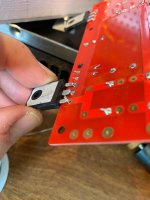
Yup: that dim-bulb tester glows, and stays on. But you got me thinking. I started fishing around for ground faults. It might be that my DMM isn't to picky when alarming: I did find several ST_V+ to chassis/ground alarms. It would go off red to black, but not black to red. I don't know why that would be. My big DIY Audio FETs (IRFP240 998K UV, and SDUR60P60WT) were real shallow on one of the P-channel boards. I solder-sucked them, with then un-enthusiastic help of the wife, we wiggled them out of there. I re-mounted them much higher up for more clearance between the bottom of the board and the aluminum heatsinks. I also remounted the whole power supply board with nylon tube/washer things for WAY more clearance between the bottom of that board and the steel chassis floor. Even after that, I still found some of those ST_V+ to ground falults: same behavior as before.As long as the dimbulbtester doesn't dim down/goes off - there is something wrong.
I would disconnect my amp boards from the PSU and would check the PSU-voltages first. With focus on their symmetry (+Vout PSU = -Vout PSU).
...
p.s.: it can take some time till I answer - I am most often busy with projects/job
I can't hang the hole day on the computer - so please, be patient with me
The one thing I did find was a misbehaving Left N-channel board.
LEFT CHANNEL
Variac at 17VAC, ST_V- to ST_V+ 2.55VDC, dim-bulb in circuit
N-ch TP2 to TP3 -0.141VDC
P-ch TP2 to TP3 0.000VDC
Variac 000VAC
FE-board TP1 to TP2 1.3ohm
FE-board TP3 to TP4 1.2ohm
Variac 017VAC, ST_V- to ST_V+ 2.55VDC
FE-board TP1 to TP2 000.8ohm
FE-board TP3 to TP4 1.5ohm
return Variac to 000VAC
FE-board TP1 to TP2 1.2ohm
FE-board TP3 to TP4 1.2ohm
Variac to 18VAC, ST_V- to ST_V+ 2.56VDC
DC offset at speaker out: 0.449VDC
RIGHT CHANNEL
Variac at 17VAC, ST_V- to ST_V+ 2.54VDC, dim-bulb in circuit
N-ch TP2 to TP3 -0.000VDC
P-ch TP2 to TP3 0.000VDC
Variac 000VAC
FE-board TP1 to TP2 1.2ohm
FE-board TP3 to TP4 1.2ohm
Variac 017VAC, ST_V- to ST_V+ 2.56VDC
FE-board TP1 to TP2 1.7ohm
FE-board TP3 to TP4 1.5ohm
return Variac to 000VAC
FE-board TP1 to TP2 1.2ohm
FE-board TP3 to TP4 1.2ohm
Variac to 18VAC, ST_V- to ST_V+ 2.55VDC
DC offset at speaker out: 0.438VDC
I double checked the measurements that I put in BOLD above, and they are correct.
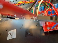
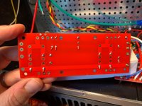
Also of note: I checked the underside of one of my N-ch boards, and it's possible the thermistor was touching one of the FET leads. I pulled the FETs, and remounted them all higher up to confirm they are not shorted.
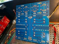
Attachments
If you have hum in the PCB (confirmed by swapping power supply leads between channels and with input shorted) it's probably a dry solder, loose contact or questionable component around the JFET inputs.
Good morning Gang, this is long but as detailed as I can be for the greatest “Thinktanks” out there. So as we all know I’m still dealing with my hum issue in the right channel of the F5T. This morning I got up totally full of **** and vinegar bound to find this issue. This is what I’ve done, why I did it and what I think I came up with. Now what to do about it?
Thank you Sangram and Dennis Hui for the suggestions.
1. Rechecked and reflowed the solder joints around the Jfets plus anything that look even partially sketchy and clean up any excess flux. tried that and tested afterwards but still have the hum.
2. Totally removed the left transformer from the stack and totally rotated the transformer powering the right channel, tested with no difference.
3. Removed the power from the terminal block and tempted in running the power completely away from the right side. Test, no difference.
4. Removed all power to the RIGHT channel transformer and tempted in wiring routed on the left side of the case totally away from the right channel and parallel the right & left side dc to the left channel psu. Test, no difference.
5. Not sure what this did but I disconnected the +dc power and stuck my ear in the speaker and there was still hum. Disconnected the -dc and total silence. Is this telling me there is an issue in the left channel of either the fe or N channel output board?
I’m thinking with all of the testing with the power that I’ve done, I’m pretty confident I don’t have a ground issue, wiring issue or shielding issue. Thoughts on this? Am I correct about the left channel of the fe or N channel output board? Thoughts on this as well. Thank you in advance.
Joe
At 6 inches distance, is there any audible noise?
If not, I wouldn't worry about it. 4mVAC is 2uW into an 8 ohm load. This is not going to make any meaningful difference in measurements or listening.
Try the shielded wire and see if it improves things.
If not, I wouldn't worry about it. 4mVAC is 2uW into an 8 ohm load. This is not going to make any meaningful difference in measurements or listening.
Try the shielded wire and see if it improves things.
Thank you Sangram, hopefully it’ll be here today, otherwise Monday.
Actually there is hum from a distance. I stick my head in the cone because I’m working on this project in my dining room with 2 refrigerators running and my wife doing things in the background as well. I want to be sure what I’m hearing. When I’m home alone and ****’s aren’t running, I can hear the hum from about 6’ back. Maybe because I’m keying in on it? My listening room is pretty well insulated and isolated from the rest of the home. I’m just thinking if I can hear it upstairs, I’ll hear it in the room between songs, or while searching for something to listen to but that’ll also drive me nuts.
Actually there is hum from a distance. I stick my head in the cone because I’m working on this project in my dining room with 2 refrigerators running and my wife doing things in the background as well. I want to be sure what I’m hearing. When I’m home alone and ****’s aren’t running, I can hear the hum from about 6’ back. Maybe because I’m keying in on it? My listening room is pretty well insulated and isolated from the rest of the home. I’m just thinking if I can hear it upstairs, I’ll hear it in the room between songs, or while searching for something to listen to but that’ll also drive me nuts.
to Mrdrewk #1073
Hello Mrdrewk,
your PSU seems o.k.. You have nice symmetrical voltages (+34,28V DC /
- 34,32V DC). Those numbers are really good!
Your frontendboard: Your resistance measurements show me, that all is dialed down (pot1 / pot2). I can't tell if any of the active devices on the frontendboard have a damage. I hope so. But I assume.
And you have that lower resistance on the frontendboard (left channel) from TP1 to TP2 (0.8Ohm). There seems also something wrong. I have to check
what could cause this.
On your Left-N-ch-outputboard you measure -0,141V DC over the bias resistor
(=TP2 - TP3). There is something wrong. Should be 0V (or very close to).
Have you checked your N-ch-Mosfets when you pulled them out?
Do you have a little Device -tester like the Mega 328 or Peak DCA75?
You could also measure at the Mosfet-legs (N-ch) if you have a low resistance to ground or to the heatsink. 😕
Greets
Dirk 😀
to Mrdrewk #1073
I think that lower resistance (0.8Ohm) on the frontendboard from TP1-TP2 is simply caused by the tolerance of the trimpot.
You can turn pot 2 and your resistance - measurement fromTP1-TP2 will go up.
Dirk
I think that lower resistance (0.8Ohm) on the frontendboard from TP1-TP2 is simply caused by the tolerance of the trimpot.
You can turn pot 2 and your resistance - measurement fromTP1-TP2 will go up.
Dirk
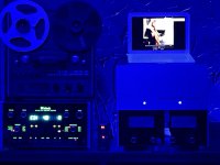
I received the shielded cable the other day, removed the old twisted pairs and installed the shielded cables. Let the amp cook a while, checked bias and offset a final time. Bias is about 355mv left channel at about 2mv’s on left and about the same on the right with -3mv offset. Time for the test so plugged in my pair of test speakers. Damn, still got that slight hum. I decided I’ll just have to live with it. Brought the amp down to my listening room to connect up. Well SOB, both channels are totally silent. No hiss, no hum, no buzz. I’m thrilled, but with?? The F5T had to be picking up something in the house circuit and producing it and perhaps I’ve been chasing a ghost. Anyway, wow, the F5T sounds fantastic. Has more authority/punch & tighter bass than the Mc it’s sitting on. The soundstage is wider, more 3 dimensional. I have to say, I’m pretty impressed. Thinking of possibly complimenting the F5T with a Linestage. Thank every one of you guys for all the help. I’m hooked!!
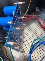
Attachments

- Home
- Amplifiers
- Pass Labs
- F5Turbo Illustrated Build Guide