Running my ACA in my main system now, pre is B1korg, speakers are LK1 Bookshelf kits 86dB/1w1m, DAC is Ares II CD, is Vincent CD-S4, streaming is via Galaxy A7. Analogue is Townshend Rock/RB250/Nagaoka MP11 via DIY Elekit MM phono stage.
Very impressed to say the least.
Very impressed to say the least.
Very quick read in Wikipedia if my examples are not clear enough:
Amplitude - Wikipedia
Thank you for the link!
Does anyone use a single ACA to power Klipsch RP-600M bookshelf speakers? These are rated at 96 dB sensitivity, but I can crank up the volume to 100% (PS Audio DAC w/ volume) and I doubt I'll get any noise complaints. It is perfectly clear and distortion-less at 100% volume too, which is amazing, but also not very loud")
Also noteworthy is that my DAC only pushes out 1.4V to the RCA outs that feed into the ACA.
I don't believe anything is wrong with my ACA, I'm just curious as to what other people are experiencing with the Klipsch RP-600M + ACA combo.
Have you tried altering the intrinsic gain of the ACA?
Increasing R12 is all you have to to do. Nothing bad will happen and the overall result may well be preferable to adding amplification in front of the ACA. Assuming you fitted a 39k originally then try a 68k, 82k or 100k. Each higher value gives more gain. An 82k will almost double the voltage output for a given input level.
Thank you for this tip. I don't know enough to understand the concept behind what you're talking about, but if it's going to give it more gain, it might be worth a try.
Does this mean I would have to de-solder then solder in another resistor at R12? Can I solder another 39k resistor in the same spot? I take it this is like running in parallel? so.... probably will not work. hahaha
I take it there there are no resistor sockets for quick change?
What Istvan said above, you'll need to unsolder the old one and solder the new one. Unfortunately there is no other way.
But it's no big deal, the easiest way is to first cut the resistor's legs close to the solder pad on the PCB, then using a solder sucker or some braid remove the remains from the pad. That way the risk of lifting a pad or damaging a component is greatly minimised.
But it's no big deal, the easiest way is to first cut the resistor's legs close to the solder pad on the PCB, then using a solder sucker or some braid remove the remains from the pad. That way the risk of lifting a pad or damaging a component is greatly minimised.
Thank you for this tip. I don't know enough to understand the concept behind what you're talking about, but if it's going to give it more gain, it might be worth a try.
Does this mean I would have to de-solder then solder in another resistor at R12? Can I solder another 39k resistor in the same spot? I take it this is like running in parallel? so.... probably will not work. hahaha
I take it there there are no resistor sockets for quick change?
The voltage gain of the ACA is approximately given by dividing the value of R12 by R11. So 39,000/10,000 is 3.9
You have to remove the resistor as others have said and then replace it with a different value. No sockets
The value of R11 (10k) sets the input impedance of the ACA. Although you could lower this one instead of raising the other to increase gain (and here you could add a resistor in parallel) the lower input impedance would need to be able to be driven OK by whatever you have feeding it.
hahaha ooops! It's a good thing I'm not bashful asking questions. Thank you!John, it will not work that way. Soldering another 39k parallel will give you 19,5k
Thank you for the tips, it's greatly appreciated!the easiest way is to first cut the resistor's legs close to the solder pad on the PCB, then using a solder sucker or some braid remove the remains from the pad. That way the risk of lifting a pad or damaging a component is greatly minimised.
I will probably wait for my preamp since it it supposed to have a higher output voltage than my DAC, but thank you for this explanation. When I try to make sense of the schematic against the board again, I will keep this in mind.The voltage gain of the ACA is approximately given by dividing the value of R12 by R11. So 39,000/10,000 is 3.9
You have to remove the resistor as others have said and then replace it with a different value. No sockets
The value of R11 (10k) sets the input impedance of the ACA. Although you could lower this one instead of raising the other to increase gain (and here you could add a resistor in parallel) the lower input impedance would need to be able to be driven OK by whatever you have feeding it.
That sounds like a plan
... and if you are feeding the ACA straight from a DAC then it would almost certainly be fine with lowering the 10k. For that you could just tag another resistor across the 10k.
Two 10k's in parallel give 5k and that would increase the voltage gain by a factor of two.
Most DAC's should be fine down to values as low as 1k or even less for a resistor tagged across.
Although we don't have resistor sockets one easy option is to use something like a Veropin which were common decades ago for constructors using stripboard. They are just a pin that would solder in place of the resistor leads and allow you to attach a resistor from the top without having to access the underside of the board.
So lots of options if needed
Attachments
Hi,
after finishing one of my ACA-kits there is one important question left: what about the DC protection? The turn-on/off noise is okay for me, and there would be a solution with a 100000uF cap. But the DC protection is not solved until now. Would the DC protection board/circuit from the store work with the ACA properly (or the question should be, would the ACA work properly)?
Thanks in advance!

You don't need DC protection as such, the ACA can not endanger a speaker with DC.
What you need is a speaker delay to stop you hearing the noise at switch on which the store circuit should do OK although I'm not sure what the recommended voltage range is... but that should be a minor issue.
It does seem a bit overkill though and the board would take a lot of space up.
Have a look at post #32 here:
A possible approach to adding a silent start/shutdown to the ACA
This could be built into the ACA with the parts neatly soldered to the relay.
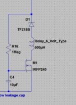
Mooly the first image with the MOSFET does not mitigate turn-off thumps; only turn-on thumps.
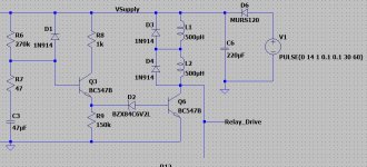
Neither does the second one with the BC547B, thanks to D6 and C6. The local supply stays high after the power is switched off, and it gradually falls according to an RC exponential decay, where C is 220uF and R is the sum of the coil resistances of the two relays. If the relays use 400mW coils, a typical value, then each coil is 90 ohms and so the RC decay time is 40 milliseconds. Way too slow when (A) the supply is an SMPS; (B) the amp is class-A biased at more than an ampere; (C) there is relatively little supply filter capacitance downstream of the On/Off switch.
Neither does the second one with the BC547B, thanks to D6 and C6. The local supply stays high after the power is switched off, and it gradually falls according to an RC exponential decay, where C is 220uF and R is the sum of the coil resistances of the two relays. If the relays use 400mW coils, a typical value, then each coil is 90 ohms and so the RC decay time is 40 milliseconds. Way too slow when (A) the supply is an SMPS; (B) the amp is class-A biased at more than an ampere; (C) there is relatively little supply filter capacitance downstream of the On/Off switch.

Mooly the first image with the MOSFET does not mitigate turn-off thumps; only turn-on thumps.
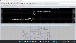
I think it would tbh. The recommended ACA power supply (the SMPS) will have a very short time constant given the high current draw of the ACA and the rails will collapse pretty smartly on power off.
As soon as the 24v rail starts to fall the relay current decreases and the 18v Zener ensures that once an 18v rail threshold is reached the relay drops out.
This shows the rail falling over 0.2 seconds.
Attachments
Each ACA channel board draws 1.45 amperes; when the on/off switch disconnects them from the SMPS, this current discharges the +24V supply rail, and the rail falls according to I = C * deltaV / deltaT.
The discharge current I equals 2*1.45 = 2.9 amperes
The total capacitance C equals 2*10 = 20 microfarads ... ... remember, the on/off switch disconnects the amp from all of the capacitance inside the SMPS
So the slope of the ramp down is (deltaV / deltaT) = (I / C) = 2.9 / 2E-5 = 1.45E+5 volts per second. That's 24 volts in 170 microseconds.
I have a feeling that if you run your simulation again, installing a switch between the supply voltage source and the supply rail (now fitted with 20uF and a 2.9A current sink), you'll find that the relay current falls to 20% of its peak value when the supply voltage is WAAAAAY below 18V. You'll also see a scary fast falling edge on the supply rail.
_
Last edited:
- Home
- Amplifiers
- Pass Labs
- Amp Camp Amp - ACA