I would check for cold solder joints first.
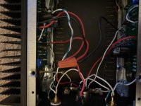
Your PCB soldering looks OK, but still worth re-flowing all solder pads.
The wiring OTH at the different terminals looks a bit iffy.
Good practice is to tin the wires before soldering them to terminals.
Not saying that this is your problem, but it is the simplest thing to do at the beginning of fault finding.
Yeah. I know my solder work isn’t the best. And the wiring is sloppy to boot. But it seems like everything is solidly connected. When I had it all apart yesterday, I tried to touch up anywhere that seemed like a possible weak connection With more solder - hence the blobby bits.
If possible, I would try to eliminate the power supply from the equation.
Well since I have this setup as monoblocks, I have two power supplies. So I swapped them out. No issue on the other monoblock and the problem still occurs on this one.
Question 1 - Is there any truth to that this has to be something on the back panel? My logic:
A. Doesn’t appear to be the power supplies since it happens the same using two different power supplies.
B. Since the issue dims the lights on both pcbs, it’s not something just on one pcb (or I would assume one LED would dim, but not the other).
Question 2 - the switch in the back is setup up to turn the power on and off. Assuming I could just connect the wires to eliminate the question of the switch? Again, I’ve since replaced the PSU Jack, so I don’t think that’s it.
Thanks for all of your input.
Jim.
Well since I have this setup as monoblocks, I have two power supplies. So I swapped them out. No issue on the other monoblock and the problem still occurs on this one.
Question 1 - Is there any truth to that this has to be something on the back panel? My logic:
A. Doesn’t appear to be the power supplies since it happens the same using two different power supplies.
B. Since the issue dims the lights on both pcbs, it’s not something just on one pcb (or I would assume one LED would dim, but not the other).
Both leads go back to the same connector. So either side can cause both to dim. Because of the common source voltage.
Question 2 - the switch in the back is setup up to turn the power on and off. Assuming I could just connect the wires to eliminate the question of the switch? Again, I’ve since replaced the PSU Jack, so I don’t think that’s it.
You can, yes. Clip across the switch.
Last edited by a moderator:
Looks cold solder joint . Took screen shot
Look around for solder splatter.. best to clean the excess so it's clear solder is done well. Mmm I always keep them clean so easy to backtrack cause I'm a noob too so extra careful
Check transistors since only a few ..light dim something might be shorted ..or kaput . Compare left and right ..if something diff ..take out and check
Attachments

Where did you get the reference that there would be a CD?
There are videos contained within the build guide. There is also a link to TekThing's YouTube channel on the store page covering the build of a previous version.
I you can be more specific about where you are seeing the word "video" in the guide - we can help you determine which video is being referenced. There are two videos I saw with a quick scan at steps 40 and 42. There may be more. Those?
The 1.6 build guide is full of references of "video" in it. Please look it over if you get a chance.
Examples:
Page 2 - While some colors are unchanged, there are now more unique color pairs, and we have updated the wiring diagrams with the new colors, however the photos and videos in the guide have not yet been updated.
Page 23 / Step 34 - However, this means the wire colors in the pictures and videos in this guide will not match the wire you have received. Please be careful to always consult your wiring guide diagram, ........
We will update the photos and videos at some point in the future, please bear with us.
Page 27 / Step 39 - WATCH THE VIDEO in the next step before proceeding. (It would be on this step but you can't have a step with videos and images together.)
Page 28 / Step 40 - Back panel wiring shown in this video. Please review before and
after you proceed.
Page 29 / Step 41 - See video in the next step for overview.
Page 30 / Step 42 - Video with overview of PCB and power wiring.
Page 34 / Step 49 - This video shows the wiring of the completed amp
Page 35 / Step 50 - Video covering power up, connections and normal operations.
Only one speaker shown because I can't fit two on my table.
Both leads go back to the same connector. So either side can cause both to dim. Because of the common source voltage.
You can, yes. Clip across the switch.
Alright. I connected two wires across the switch (One for each side) with the switch off and powered it up. The issue with the amp powering down still happens.
Then I disconnected one of the jump wires at a time, and each side of the amp did not blink on and off at all when only one jump wire was connected and the amp was switched off.
I had assumed that at least one side of the amp when connected this way would reproduce the issue.
Once I removed the jump wires from across the switch and powered it back up, it started to blink on and off again.
Damn.
Jim.
zapmehome - I looked it over briefly, but I'm not sure what you need. All the references to "video" mentioned are covered in the videos contained within in the guide. You made all the effort to type the information, so I assume there's something you still need.
I'll ask another way: Do you have a specific question about your build that is not answered in the guide? What can we help with?
I'll ask another way: Do you have a specific question about your build that is not answered in the guide? What can we help with?
Jim perhaps your switch is somehow shorted to ground internally. It sounds like the amp boards are OK. Something that gets the voltage from the input connector on the back panel and the power input leads to each amp.
I think I uploaded a picture to show you what I did to get around the issue you describe, which is identical in nearly every way to your issue.
I eliminated everything in the path and it works great. I have mine on a switched power strip.
I think I uploaded a picture to show you what I did to get around the issue you describe, which is identical in nearly every way to your issue.
I eliminated everything in the path and it works great. I have mine on a switched power strip.
Attachments
Zapmehome - just to clarify, you are looking here; ?
Amp Camp Amp V1.6 Build Guide - diyAudio Guides
The images in step 40, 42, 49 and 50 are videos. Touch or click to play.
Amp Camp Amp V1.6 Build Guide - diyAudio Guides
The images in step 40, 42, 49 and 50 are videos. Touch or click to play.
Jim perhaps your switch is somehow shorted to ground internally. It sounds like the amp boards are OK. Something that gets the voltage from the input connector on the back panel and the power input leads to each amp.
I think I uploaded a picture to show you what I did to get around the issue you describe, which is identical in nearly every way to your issue.
I eliminated everything in the path and it works great. I have mine on a switched power strip.
Yep. Thanks for that, I think I get what you are doing, I just didn’t want to mess with the PSU. It may be my only option tho.
Worse things have been done. Obviously the right way is to source another connector and or switch. Both ways work. And will say again I used too much heat on my back panel connector. During the troubleshooting process I broke one of the terminals on my switch. Since the amps are on a power strip anyway it was a quick way to get back on the air. : )
@hamelka
Jim,
You can do a simple test to check the switch for a short to the chassis/case. Just undo the nut and push the switch inside. Make sure the metal toggle and frame does not touch any thing, maybe wrap a turn of tape round it. If you connect it up and the problem is gone - the switch at fault. If the problem is still there it is not the switch...
- Home
- Amplifiers
- Pass Labs
- Amp Camp Amp - ACA