Thank you Zen Mod! I will have a very close look at that. Simpler is always better.
Bfcpa,l I agree with you. I'm not going to make any changes to this amp. I was just looking down the road, wondering what to do with all these partially matched sets of transistors.
If you are looking for more matches to the ones you got from me then I have more that are close to the same VGS values.
Zen Mod,
Do you mean trimpot P3 in the V3 amp? I can't find any other iteration.
yup
That's what I am building!
My question was actually meant for a later time, when I know a bit more.
If each output MOSfet had a trimmer that allowed for setting bias voltage independently, then one could use mis-matched MOSfets. Just set these bias pots so that each of them create the same voltage drop over the source resistors.
It seems to me that the bias circuit would work fine, if there were 4 trimmers, each of 4K. To the resistors R5, R6, they would appear as a single 1K trimmer.
Not sure though how easy it would be to bias them as the bias would drift each time you fired up another MOSfet.
Probably file under crazy....
Think about how you would adjust to a zero offset after you got all the Ns adjusted then started adjusting the Ps, trying to keep all source resistor voltages equal. You'd be trying for weeks! 😱 Absolutely no reason or benefit for doing what your asking. Just use matched JFETs, match MOSFETs N to N, P to P, use low tolerance source resistors or match them, bias it and enjoy. 🙂
Here is the procedure: Assuming all mosfets have a bias trimmer.....
You turn all Vgs to zero so the outputs do not conduct. Then you bias 1N and 1P MOSfet pair to somewhere just under the end operating condition using the regular procedure. Let it cook.
Then bias another pair. Let it cook. The first pair will conduct a bit more, hopefully not too much, which is why you biased under operating temp. If they do go up too much, turn them *both* down a little. Don't touch any other pairs.
Then bias another pair continue until done.
I mean you should get very close. With some of the matched sets I have, the voltage across the source resistors is actually pretty different, even though they turn on at the same time. eg. 3.0 to 2.64. That's gotta be due to different gm.
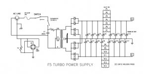
In looking at the power supply from the F5Turbo article, I wondered, what happens if you don't attach the transformer's center tap to the zero volt line?
Attachments
Last edited:
Thanks 6L6... so my transformer must be different somehow? I have grounded the output of the cap bank, jus not the transformer CT. The PSU that works,.
Transformer Specs attached.
Transformer Specs attached.
Attachments
Last edited:
If your PSU works and has a stable ground, you don’t have your transformer attached in the manner shown on the schematic you posted in #5526.
Which leads to the question, how DO you have it attached, with the 5 secondaries...??
Which leads to the question, how DO you have it attached, with the 5 secondaries...??
I have a weird issue.... I think it is interesting, but not yet solved for sure....
One channel with Fairchild parts matched using Vgs threshold can be biased.
The other channel with IRF240 and 9240. Each polarity was Vgs matched while running at 1 amp and 50 degrees C. The bias voltage at this current is around 4V.
This channel does not bias up nicely.
When biasing the amp output would show DC offset which I could zero with the other pot, but the meters across the source resistors did not stray from 0 mv.
Move the clips to the other channel, and no problem.... the meters work fine. Clearly, the two outputs I was measuring had not yet turned on....
I suspect that only one pair of the new transistors has turned on, and I've just not found which ones they are.....
Hmmmm, perhaps they all won't turn on when one set has met the max allowable 0.4 V bias across the source resistors? So these would work great, provided that you don't use diodes.....
I have another set that are Vgs threshold matched I can swap into place, but the poor boards are taking a beating.....
I'm going to try finding the pair of devices that are on.
In any case, since gm is not matched, there will be one MOSfet output that will show the highest voltage drop across the source resistors.
If your PSU works and has a stable ground, you don’t have your transformer attached in the manner shown on the schematic you posted in #5526.
Which leads to the question, how DO you have it attached, with the 5 secondaries...??
Just like the diagram shows. .
One V+/CT/V- secondary is not used. The 4 other secondaries are split into two groups and run in parallel. There is one full wave rectifier per channel.
The caps are strapped together on the PCB boards. They are the white teabag boards. There is a pair of boards per channel.
The ground on the right hand side of cap bank as shown on the diagram goes to the ground connected to the diode bridge/CL-60. There is one diode/CL-60 per channel.
Both of the diode/CL-60 grounds are connected to the same earth point on the chassis where the safety earth comes into the box.
I hope the drawing is OK.
Attachments
drawing is not ok to see it clearly. it is tough to see how you hooked them up.
i would feel there could be something wrong but can not indicate it.
i would feel there could be something wrong but can not indicate it.
The secondaries are in parallel with the other secondaries. If they were not, fuses would be blowing.
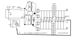
The connection between the center tap and the zero volt line on the left of the cap bank is not made.
The ground on the right of the cap bank is connected directly to the ground on the left on the diode/CL-60. The other side of the diode/CL-60 is connected to earth.
This shows only secondary side and ground.
Attachments

Last edited:
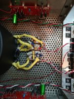
does the re-drawing help? The build is a mess.... The first photo shows a terminal strip. With secondaries attached. The unused ones have heatshrink wrapped ends. The flying caps/resistors are snubbers.
One pair of red/white goes to a cap bank for each channel. The second is a closeup of one of the cap banks. You can clearly see that red and grey are +/-. No CT connection on the diode bridge side.
There are a lot of relays around the boards. The notion was that in the event of a short cycle while powering up, a relay would disconnect the diode bridge from the cap bank, to enable the thermistors to cool.
But this is not about the relays. This is about parallel secondaries of a CT transformer, still supplying the correct voltage, even though the CT is disconnected.
The secondaries are 2xV apart. The zero volt line is connected at the signal ground only. That gives the center voltage reference. Then V+ is V above signal ground ,and V- is V below. The signal ground is 10R above earth due to the CL-60.
So there is a center reference.
Attachments

Last edited:
Well, I decided to trust my meters, and the new channel biased up BEAUTIFULLY. Unfortunately, noisy.... 1.25mV ( channel with meters attached ) and 0.775 mV rms, according to the entry level Digital scope.
Now, onto grounding schemes....
Although I may have little luck with two channels and multiple secondaries in one box.
Also, this is with the output boards wired in parallel, which will certainly increase loop area.
Thanks for all the help!
I've got to go learn a bunch of stuff now.
Now, onto grounding schemes....
Although I may have little luck with two channels and multiple secondaries in one box.
Also, this is with the output boards wired in parallel, which will certainly increase loop area.
Thanks for all the help!
I've got to go learn a bunch of stuff now.
Last edited:
RE: grounding the center tap.
I found this online. EEVBlog entry
This mainly depends on the transformer and only after that comes if you like supplies with grounded outputs. If you let it float the transformer needs to be rated for use in class II appliances (double / reinforced insulation). You'll find that information sometimes on the nameplate of the transformer or you can see that it's a doubly insulated transformer (separate coil chambers, insulation to core etc.). If unsure, ground it.
Last edited:
If you are looking for more matches to the ones you got from me then I have more that are close to the same VGS values.
Thanks! Maybe next payday...
I have a problem, I don't know what to do about....
I biased the amp with shorting plugs, in place DC offset is about 8 mV -- not quite finished biasing....
However, after turning the amp off, removing the shorting plug from the channel and turning the amp back on, the DC offset goes to 0.25V, or 250 mV.
The right channel is fine.
What can this possibly be? If this was intermittent gate, it would happen whether or not the shorting plug was in place. If it were mismatched parts, it would also be present whether or not the shorting plug was in place.
What could cause this? Any help would be *most* appreciated.
- Home
- Amplifiers
- Pass Labs
- F5 Turbo Builders Thread