I have a (dumb) question regarding the schematic shown. if the 150 ohm resistor is replaced with a 80 ohm one, using a 12 V PSU, how does one get 250 mA current flowing thru the circuit?
Regards,
There are no dumb questions. In general the 150 ohm resistor is a current limiting resistor. Lower value allows more current to flow. Now that you mention it though that number doesn't look right. I'll have to go and check my notes...
TJ
I apologize for bogus numbers. 81 ohms was ~130 mA (10.59v across resistor), 26 ohms gave ~380 mA (9.90v across). Both supplied ~13.80v from a "12v" power supply. The theory is right but the numbers were from memory...which isn't as good anymore.
I need to be more careful when posting.
TJ
I need to be more careful when posting.
TJ
The MOSFETs need to be matched for Vgs (Voltage gate-source, the voltage at which the mosfets turn on), within a 1/10 volt or so (0.1), so one of the pair doesn't turn on before the other one and take all the current - if that happens basically the first mosfet will do all the work.
The N channel need to be matched to the N channel, the P need to be matched to the P. There is no need to match N to P, and although it's possible, it's quite rare.
Use the mosfet matching circuit as shown in the article you linked, don't try to use the front-end, it won't work. You can use a DC wall wart as suggested for power, there's not a lot of current required.
The articles that Nelson Pass writes all say Vgs matching is done at or near operating conditions.
The Vgs you describe when the MOSfet turns on is the threshold voltage or pinch off voltage Vgs(th) or Vth.
It does not guarantee that the mosfets will share the work at load, as they have varying transconductance.
To add: Even if you do match Vgs at operating conditions, that says nothing about the pinch off voltage, as those parts can have different gm and therefore different V(th).
If you match Vgs and Vth, you've got well matched parts.
If you match Vgs and Vth, you've got well matched parts.
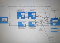
Attached is a proposed wiring scheme. The important bits are:
1) Power supply ground is attached *directly* to system ground ( the diode bridge ) with a single wire.
2) Output board grounds from board 2 and 4 are attached to FE board ground point, then to system ground ( the diode bridge )
3) V+ and V- is connected from power supply to OP boards 1 and 3.
4) V+ and V- is connected to FE board from OP boards 2 and 4.
PS ground is not transmitted through OP boards. It is an independent wire to system ground.
Any comments would be HIGHLY appreciated!
Attachments
jpg attached.
Oops! Sorry for posting the wrong file format.
Any help here would be awesome. You guys have been great.
Thanks for your patience.
Erik
PS, it's wired funny this way, because the cap bank is on the front side of the amp, and the FE board is on the back side. There is a large transformer in the middle. If anything is confusing, please let me know and I will clear it up.
Attachments
Last edited:
This will help immensely... http://hifisonix.com/wordpress/wp-content/uploads/2019/02/Ground-Loops.pdf
Thank you 6L6! I will get on that ASAP.
It's my wife's birthday today, and one kid is home from University. My wife is 30 with 27 years of experience.
It's my wife's birthday today, and one kid is home from University. My wife is 30 with 27 years of experience.
This will help immensely... http://hifisonix.com/wordpress/wp-content/uploads/2019/02/Ground-Loops.pdf
Omg that's a lot to learn. Really complicated.
I've read about a third or so. It's not so bad, but then again, I don't know this stuff..... There are some questions coming up, but maybe finishing it will answer them.
For sure, you need to know how the circuit was implemented so that the HBR resistor can be inserted in the right place.
For sure, you need to know how the circuit was implemented so that the HBR resistor can be inserted in the right place.
Last edited:
Are the humbreaking resistors supposed to be inserted between the junction of R3/R4 and the audio signal ground?
Page 56 of http://hifisonix.com/wordpress/wp-content/uploads/2019/02/Ground-Loops.pdf should answer your question, the lowest bridge & cap in the bottom right corner are replaced with a CL60 in the FW designs.
Thanks Itsmee. Pages 36 and 37 are more detailed. I think 56 assumes that the amps are on a single PC board, while the F5T is spread over a couple.
My question is where on the FE board to attach the HBR.
Is it just at the GND point or is the GND point on the FE board on the wrong side of the feedback resistors ? ( I am at the office, so cannot check )
My question is where on the FE board to attach the HBR.
Is it just at the GND point or is the GND point on the FE board on the wrong side of the feedback resistors ? ( I am at the office, so cannot check )
Last edited:
...My question is where on the FE board to attach the HBR...
You don't, it's in the PSU between 0V and chassis earth, unless your talking about low value resistors (10R ish) in the ground connection between the input socket and ground on the PCB; only do that if you have hum problems you can't cure any other way.
Hi Itsmee,
I have the diode bridge and CL60 in place already.
There is hum I'd like to get rid of, but before installing the HBR though, there are quite a few other things to implement -- proper wiring being one of them -- like a proper star ground or 'T'.
My main issue is space in the amp. I built the case to fit a stand, and that meant I had to either mount the transformer on the face plate, or mount the cap banks on the face plate. I chose the cap banks, since then the diode bridges had easy heat sinking. But that put the transformer in the middle of the amp.
I'm going to measure the noise with a QA400 as I go, to test for any changes.
Adding the 10R's may not help, thats for breaking hum loops, if it does, rewire.
Your problem may be induced hum from local proximity, first move the wiring, then try rotating the transformer, next try standing it vertically - it moves the flux lines by 90°, try both N-S & E-W 'doughnut hole' orientation to see which gives the least hum; decide from there what needs to be done.
Your problem may be induced hum from local proximity, first move the wiring, then try rotating the transformer, next try standing it vertically - it moves the flux lines by 90°, try both N-S & E-W 'doughnut hole' orientation to see which gives the least hum; decide from there what needs to be done.
It looks to me like the FE board needs to be modified for the HBR to be installed as per the Hiphonics article. Specfically, the article shows that the RCA shield is connected to the HBR on it's way to the zero volt line, as does the ground between R3 and R4 ( I think ).
A picture says a thousand words.... attached is how I think the HBR should be added. The diagonal line is the HBR, the thick ground is cut, and the link and group of G's are connected. It is labelled with black text.
BEWARE: I'm not an expert. Just trying to learn something. It's easy enough to operate as designed.... just replace the HBR with a jumper.
Does that look right?
Attachments

Last edited:
Can't help with the PCB, I dont know it - haven't built one with those boards.
There are lots of sucessful builds without the HBR.
Pictures of your build would help.
There are lots of sucessful builds without the HBR.
Pictures of your build would help.
Right now, I am working at cleaning up the power supply... again. I used a bunch of crimped push on connectors, and a nice tool, but it was just as powerful as a set of pliers.. So, I am soldering them all on, and heatshrinking after.
Four literally fell off the wires. I am amazed it was working.
I will be posting some shots once it's working again. And I do want to measure it again... I did 6 years ago, but I am a bit more cautious/scared these days.... I am slowly learning how little I know.
Four literally fell off the wires. I am amazed it was working.
I will be posting some shots once it's working again. And I do want to measure it again... I did 6 years ago, but I am a bit more cautious/scared these days.... I am slowly learning how little I know.
- Home
- Amplifiers
- Pass Labs
- F5 Turbo Builders Thread