If you take the diodes out, an amp with a 40 V rail can deliver up to 46.5 A across the MOSFET Rds + Rsource_resistors. With the diodes in place, that rail can deliver 106 A over Rds.
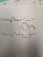
Attached is the idea for a little circuit that might stop damage due to these surges , and stop damage due to crazy DC offset at the speaker terminals (fuses + relays). No doubt, a resistor ladder will need to be in place for the relay coil voltage.
Any idea if this will work?
Attached is the idea for a little circuit that might stop damage due to these surges , and stop damage due to crazy DC offset at the speaker terminals (fuses + relays). No doubt, a resistor ladder will need to be in place for the relay coil voltage.
Any idea if this will work?
Attachments
Last edited:
You mean with the coil across the rails?
The relay may not open at half the rail voltage. Specs show guaranteed opening voltage can be as low as 10% of coil voltage.
The relay may not open at half the rail voltage. Specs show guaranteed opening voltage can be as low as 10% of coil voltage.
What would be the current path? the supply may be at 0V potential but it isn't connected to it.
Sorry, I don't get the question. If the supply is off then the relays are open. If the supply is on then the relays close. If. The fuse blows on one rail, the relay opens on both.
Last edited:
Ooo! That pic with all the parts just sitting there, but with the potential to make some of the sweetest sounds ever, is very sexy! LOLMy F5T v3 Balanced mono blocks with separate power supplies.
Some assembly required.
I'd like to match some output mosfets. Does this make sense? Or is it just stupid.
Should I just solder pcb to screw terminals onto the output boards and match outputs by measuring across the source resistors of each MOSFET under test as I try to bias them? The diodes would still be in place. I could match a pair at a time.
Otherwise, I am thinking of a harness to connect Vgate, V+,GND or Vgate,V-,GND from the FE board to the output MOSFETS mounted on the actual heatsink that will be used in the amp.
The 0.5 ohm source resistors would still be in play for measuring bias current.
With the harness:
Can P1 or P2 then be used to vary Vgs to match MOSFETS?
Can the FE board be powered without the output boards attached?
Does the 47.5 Ohm gate stopper resistor need to be used in matching?
Will the missing feedback cause issues with the FE board?
Sorry, I don't get the question...
1 relay will work, if a fuse blows, one end of the coil is connected to a supply (+ or -V), the other end of the coil is flapping in the breeze, there's no where for the current to go.
Thanks 6L6 I've seen that one.
My question is specifically if we can use the Front end board to drive the MOSFETS and do the matching via P1 or P2 and use the F5T power supply as the power source.
Why? I have no lab power supply.
So the big question is if the FE board can run without feedback from the output board, and P1/P2 still modulate Vgate+ and Vgate-.
Using a couple damaged output boards, attach the MOSFETS using PCB connectors, and jumper the gate stoppers.
By jumpering V+ to a second board, 4 MOSFETS could be tested at once.
1 relay will work, if a fuse blows, one end of the coil is connected to a supply (+ or -V), the other end of the coil is flapping in the breeze, there's no where for the current to go.
One coil is connected V+ to ground the other is V- to ground.
A resistor ladder can be used as necessary to adjust the voltage for each coil. eg. a 36 volt rail and a 24 volt coil would use a 1/3, 2/3 split, with resistor wattage and values to respect the coil draw.
with A class amp as load , it's usual to have ratio of approx. 1.25 , AC to DC
so with 25Vac secondaries , expect something as 31.25Vdc at caps
so with 25Vac secondaries , expect something as 31.25Vdc at caps
with A class amp as load , it's usual to have ratio of approx. 1.25 , AC to DC
so with 25Vac secondaries , expect something as 31.25Vdc at caps
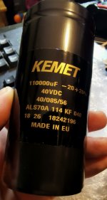
Ok, thanks Zen Mod so that should go well for the F5T V2 I can put all the capacitors in Kemet 40v
Matching mosfets using the FE board can only be done with the actually built up amp, as part of the biasing procedure. Only change is to add a PCB mount terminal for the outputs....
There is no way to isolate the feedback from the front end.
Seems better to buy a lab power supply capable of providing rail voltage or use the amp power supply only. Not the FE board.
There is no way to isolate the feedback from the front end.
Seems better to buy a lab power supply capable of providing rail voltage or use the amp power supply only. Not the FE board.
Last edited:
Or you could find a simple, inexpensive 12 Vdc wall wart, maybe laying around somewhere, with a current rating of 500 mA or more and a 3-5W resistor of a value that gives the desired current to the DUT. High precision isn't required, only consistency. You're not going to measure and compare to anything other than the group of devices you're measuring against. In other words your measurements are only good for you, they can't be compared to anyone else's and frankly don't need to be. You just want devices that that match each other using your setup.
Below is a great, simple circuit for matching MOSFETs. For 12vdc I use an 81 ohm 6 W resistor (actually 2 x 3 W 162 ohm, 80 ohm is fine) for about 250 mA at 12 Vdc (actually ~13.8 Vdc). With that, the DUT will heat up to around 50-55c max without a heat sink and closely represents the conditions inside an F5T and therefore a very good match under actual operation. Let them cook for 10-15mins to stabilize then note the Vgs.
*Edit: I would not use the FE board for matching.
TJ
Attachments
Last edited:
Thanks for the ideas Takitaj!
Will that provide a close enough match? My voltage is a bit more than 36 and each runs at max 1.2 amps.
With "fast on" tab connectors for the power supply, it is easy to make a harness to connect two damaged output boards with PCB terminals ( no diodes ) and drive 4 mosfets at once under actual operating conditions of Ids and heatsink temp.
With a trim pot to bias each transistor independently, ( cut Vgate trace in half ) measure Vgs directly from each mosfet at the desired Ids as the heatsink is held at operating temperature. This rig may even be used to adjust the values of the source resistors....
It looks to me like the V3 output boards are the same for both polarities, so you just need to flip around the power to test the other polarity. ( Forget about the thermistor circuitry -- ie don't stuff it ).
There are issues to deal with.... ie, there needs to be a sink for the MOSfet output current, or it won't flow. The outputs of both boards need to be connected to the system ground. (The other channel should be un-powered ).
If matching 2 N and 2 P channel devices, following the F5 biasing procedure would minimize current flow to the system ground. Current will just flow between the rails.
In the final product, any difference will show up as a DC offset. Even if the DC offset is zero, the system ground may be humming with ripple and noise from the rails that you can't see with a DVM, as you are measuring DC....Likely, that noise will make itself known at the speakers if it is there in the final product.
That biasing arrangement could be very accurate... ( and safe? )
But it is probably best and safest to implement this mosfet matcher:
http://www.firstwatt.com/pdf/art_mos_test.pdf
Excellent article.
Last edited:
The MOSFETs need to be matched for Vgs (Voltage gate-source, the voltage at which the mosfets turn on), within a 1/10 volt or so (0.1), so one of the pair doesn't turn on before the other one and take all the current - if that happens basically the first mosfet will do all the work.
The N channel need to be matched to the N channel, the P need to be matched to the P. There is no need to match N to P, and although it's possible, it's quite rare.
Use the mosfet matching circuit as shown in the article you linked, don't try to use the front-end, it won't work. You can use a DC wall wart as suggested for power, there's not a lot of current required.
Or you could find a simple, inexpensive 12 Vdc wall wart, maybe laying around somewhere, with a current rating of 500 mA or more and a 3-5W resistor of a value that gives the desired current to the DUT. High precision isn't required, only consistency. You're not going to measure and compare to anything other than the group of devices you're measuring against. In other words your measurements are only good for you, they can't be compared to anyone else's and frankly don't need to be. You just want devices that that match each other using your setup.
Below is a great, simple circuit for matching MOSFETs. For 12vdc I use an 81 ohm 6 W resistor (actually 2 x 3 W 162 ohm, 80 ohm is fine) for about 250 mA at 12 Vdc (actually ~13.8 Vdc). With that, the DUT will heat up to around 50-55c max without a heat sink and closely represents the conditions inside an F5T and therefore a very good match under actual operation. Let them cook for 10-15mins to stabilize then note the Vgs.
*Edit: I would not use the FE board for matching.
TJ
I have a (dumb) question regarding the schematic shown. if the 150 ohm resistor is replaced with a 80 ohm one, using a 12 V PSU, how does one get 250 mA current flowing thru the circuit?
Regards,
I have a few questions regarding my F5T v3 balanced amplifier. I've started on the power supplies first, I'm using the diyAudio store power supply PC boards with Vishay MUR3020 diodes. They have three leads out of each TO-220 package,
1- Do I solder all three legs of the diodes to the circuit board along with the two pins for the heat sinks?
Since I'm using 800VA 36v secondary torroids, I estimate the rails will be 48vdc.
2 - With the speaker protection circuits, should I use 48v relay windings?
3 - I bought 2 sets of the F5T transistor kits from diyAudio store. Do I need to match these?
4 - I also bought the JFET's matched pairs, enough for the 4 FEB's. Once again, do I need to match these?
Thanks for the help, I'd be lost about now without this community.
- Home
- Amplifiers
- Pass Labs
- F5 Turbo Builders Thread