Btw itsmee, the link and ground are the grounds on the F5T schematic. The simplest way is to install a 2 pole PCB terminator. Link to ground and ground to star/T. Put the resistor at the T ...
Last edited:
Simplest is to use a fast on tab between G and Link, then put the HRB in series with the zero volt line.
At least that's how the diagram looks to me.
At least that's how the diagram looks to me.
Simpler still is to just attach the HRB between the FE board ground to the star/T ground, with the G/Link connected.
Sheesh, how easy is that?
Sheesh, how easy is that?
....and potentially very wrong depending on how the grounds are wired.
AFAIK, the grounds ought to be wired as follows. I will be doing it this way.
These are listed as if attached to a "T" not a star....These are listed as dirtiest to cleanest and ordered by closest to furthest from audio signal ground ( the diode bridge + CL60 ). Bear in mind that my audio signal ground is located at the back of the amp, not at the front, close to the Power supply. This method minimizes the ground wire run lengths overall.
1) Power Supply common -- direct to Audio signal ground
2) Speaker return -- direct to Audio signal ground,
3) FE board ground -- lower pair in group of 4 to audio signal ground.
4) Output board grounds -- to FE board upper ground pair
5) FE board decoupling caps common ( part of PCB already )
6) FE board feedback audio signal ground ( Link )
7) RCA shield audio signal ground ( G )
Since the only items that require ground on the output boards are the Caps, these wires can be thin.
Last edited:
OK, so I wired it that way.
With a shorting plug, and AC coupled, the scope says the noise is 200 uV rms, or 0 using case ground, ie earth, as reference. That's the resolution of the scope I guess.... low end Rigol digital scope.
I'm letting this cook right now, and tackle the other channel later.
The article linked to by 6L6 is key. I have still not implemented all of the ideas.
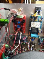
This is a photo of how the FE board was wired.
With a shorting plug, and AC coupled, the scope says the noise is 200 uV rms, or 0 using case ground, ie earth, as reference. That's the resolution of the scope I guess.... low end Rigol digital scope.
I'm letting this cook right now, and tackle the other channel later.
The article linked to by 6L6 is key. I have still not implemented all of the ideas.
This is a photo of how the FE board was wired.
Attachments
Last edited:
Could be awhile.... I just screwed up the other channel bad. Fire on board.
I was having some trouble, and suspected an N-channel short somewhere.
I removed all of the output boards from power by physically unsoldering the power wiring from the boards. I was going to reattach until failure, but thought that was a bit extreme.
I removed the FE board to check if I had made a wiring fault when repairing a feedback resistor -- I was checking just to be thorough. So the gates lines were in the air, along with the rest of the harness. The other board channel was disconnected from power at the transformer. Just the single channel was being worked on. Remember, V- and V+ were unsoldered from the boards.
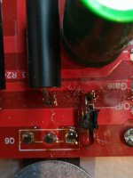
The amp was off for over 1/2 hour. There was a pop and a fire under C2x. Smells like burnt silicon....I have no idea what could have happened. Vneg was not connected to the board -- and still pop and fire..... Even if you power these caps backwards, it should be fine... they are 50 volt bipolar. Power supply is max 41 volts unloaded...
I was having some trouble, and suspected an N-channel short somewhere.
I removed all of the output boards from power by physically unsoldering the power wiring from the boards. I was going to reattach until failure, but thought that was a bit extreme.
I removed the FE board to check if I had made a wiring fault when repairing a feedback resistor -- I was checking just to be thorough. So the gates lines were in the air, along with the rest of the harness. The other board channel was disconnected from power at the transformer. Just the single channel was being worked on. Remember, V- and V+ were unsoldered from the boards.
The amp was off for over 1/2 hour. There was a pop and a fire under C2x. Smells like burnt silicon....I have no idea what could have happened. Vneg was not connected to the board -- and still pop and fire..... Even if you power these caps backwards, it should be fine... they are 50 volt bipolar. Power supply is max 41 volts unloaded...
Looks like Vgate and V- or V+ touched -- maybe on the case..... Two fried gate resistors and obviously, fried output devices.
Attachments
Last edited:
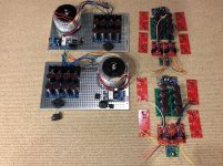
My F5t v3 Balanced amplifier picture #2, all the boards stuffed, two 800 va 36v x2 secondaries. Separate power supply enclosures and amplifier enclosures. I'm going to build the power supplies first along with the umbilical cables first. Nice to have the perforated lower plate makes it easy to build.
Attachments
Can't wait to see how this works out. Not that I want to try it, as I have yet know found every way to blow up a single ended amp!
In the end, is the speaker protection going to be beside the FE board?
And is the power supply reservoir in the amp boxes going to have just one +/-/G output?
In the end, is the speaker protection going to be beside the FE board?
And is the power supply reservoir in the amp boxes going to have just one +/-/G output?
My F5t v3 Balanced amplifier picture #2, all the boards stuffed, two 800 va 36v x2 secondaries. Separate power supply enclosures and amplifier enclosures. I'm going to build the power supplies first along with the umbilical cables first. Nice to have the perforated lower plate makes it easy to build.
plates need to have edge pointing up
that way , if you elevate them slightly from heatsink brackets , you're gaining some clearance and you can route mains wires underneath plate
see here (post #669) Babelfish M25, SissySIT - general building tips and tricks
Got it. Love the pictures of the SIT, especially the DUCATI capacitors. With that name, they look as good as they must work. Thanks.
Looks like an mur3020 was not properly insulated on the N channel. Non-infinite ohms from heatsink to pin 2. I don't know how I missed this when re-aassembled. Probably because it was fine before last output device failure.
Heatsink is earth, audio signal ground has cl-60. That short would dump Vneg to earth, lower ground potential and other polarity of power supply would appear to read double, as it did before the first slow blow fuse went.
Will repair next week.
I hope that this experience might help someone else debug their work. Lesson learned.... just because it was fine last time, does not mean it is still fine after you touch it. No shortcuts. Measure it all.
Well, I got to it earlier.
Seasoned builders will already know this....please ignore or correct if you like.
The diodes are connected to the power rails via their middle pin. The middle pin is also conneceted to the back of the diode, which means you must isolate this from the case/heatsink, or you will short the power to the heatsink.
It is easy to test if the case is connected to the middle pin with a DMM. Just measure ohms with one probe on the case and the other on the middle pin. If your sinks are anodized, you will have to find a screw hole or scratch through to bare metal to make contact. ( Plus one for anodized sinks..... anything causing a short must penetrate the anodization to make a short as well, just don't rely on it. A little insurance is better than none.)
Since all diodes on one polarity are connected, the middle pin of any diode will show zero ohms (a short) if the back of any one (or more ) diodes are shorting to the case. If there are two boards per polarity ( ie 4 per channel ) you will have to first separate the boards of the polarity under test to determine which of them ( or both ) have shorted diodes.
DO NOT remove the boards from the case. You need the short to be there to find it.
I got lucky. When the clamping pressure on one of the diodes was reduced, OL (open loop ) showed up on the meter. When tightened, it showed near zero ohms again. Just the resistance of the leads was displayed. Note, anything that shows an OHM reading means there is a short. Only OL is acceptable -- or whatever your meter reads when there is no connection between the two points.
Visually, the keratherm showed zero signs of damage; the "puncture" that connected the back of the diode to the heatsink could not be found. Only this measurement showed the short.
I replaced the insulator with a new one, wiping down the surface first, and the meter showed OL after tightening.
Last edited:
You should always wipe down your heatsink with some alcohol and a microfibre cloth or soft rag to remove any metal dust and oils etc that might cause problems for the insulator. Check all the mounting holes for burrs if you purchased the heatsink already drilled/tapped. If drilling and tapping the holes yourself always chamfer the edge of the hole so the top of the threads stay just below the surface. This prevents rough edges on the rim of the tapped holes. Clean your tapped holes to get all the filings, oil etc out. That paste of cutting fluid and aluminum filings that gets in the threads is conductive. When I built my F5 monoblocks I did all the tapping by hand. It’s a lot of work. If doing it again I would probably just buy the deluxe chassis
Thanks Bfpca, I did all the tapping and drilling by hand. Some 160 holes or more, as my case is also drilled and tapped by hand. Going forwards, I will do more than just lapping the holes in the heatsink with a diamond stone.
---
Oh, and if you want to test for diode shorts before firing it up, you will have to lift the earth side of the audio signal ground diode contraption. You could test each polarity on each channel with a single measurement.
------
I have a question for the pros, if they could be so kind....
If I wanted to install a bias pot *for each transistor* does the 1K R5 and R6 change to 4K? If it works, I should be able to use unmatched parts..... Matchining VGS(th) together with the 4 pots should be perfect, yes? no? Can easily be installed with copper tape and a small drill.....
Crazy/inexperienced or OK but not needed....?
Thanks, any comments are *very* appreciated....
look at last iteration of F5 with third trimpot (that one across input JFet source resistors) .... that is a way to go
so , just one additional trimpot, everything else stays the same
so , just one additional trimpot, everything else stays the same
Thanks Bfpca, I did all the tapping and drilling by hand. Some 160 holes or more, as my case is also drilled and tapped by hand. Going forwards, I will do more than just lapping the holes in the heatsink with a diamond stone.
---
Oh, and if you want to test for diode shorts before firing it up, you will have to lift the earth side of the audio signal ground diode contraption. You could test each polarity on each channel with a single measurement.
------
I have a question for the pros, if they could be so kind....
If I wanted to install a bias pot *for each transistor* does the 1K R5 and R6 change to 4K? If it works, I should be able to use unmatched parts..... Matchining VGS(th) together with the 4 pots should be perfect, yes? no? Can easily be installed with copper tape and a small drill.....
Crazy/inexperienced or OK but not needed....?
Thanks, any comments are *very* appreciated....
Erik, I think you should consider staying with the proven recipe for the F5 and see how you like it. After listening for a while and getting a feel for the biasing procedure and sound etc. you could then look at making changes to layout and circuitry.
This is a tricky build to get right and putting in a bunch of unknown variables just makes a good outcome much more difficult.
Thank you Zen Mod! I will have a very close look at that. Simpler is always better.
Bfcpa,l I agree with you. I'm not going to make any changes to this amp. I was just looking down the road, wondering what to do with all these partially matched sets of transistors.
Bfcpa,l I agree with you. I'm not going to make any changes to this amp. I was just looking down the road, wondering what to do with all these partially matched sets of transistors.
- Home
- Amplifiers
- Pass Labs
- F5 Turbo Builders Thread