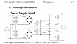
Mine is slightly different. His doesn't have the transformer snubbers and I'm not sure of the purpose of the bypass caps on the output.
I put snubbers on the transformer, per the Quasimodo thread: Simple, no-math transformer snubber using Quasimodo test-jig
I've got a few boards, you can PM me if you're interested.
I put snubbers on the transformer, per the Quasimodo thread: Simple, no-math transformer snubber using Quasimodo test-jig
I've got a few boards, you can PM me if you're interested.
Attachments
Hi,
I got 2 questions:
- Is it ok to put 3300/25V caps instead of 35V on the phono board ? 7924/7824 are for +/-24Vdc, so I think some very good and long life 25Vdc Panasonic FR would be fine.
- Is it ok to use a 22µF/25V silmic 2 or bipolar Nichicon Muse ES with R14 to stabilize offset ? I got some in stock.
Thanks
Damien
Pass DIY Addict
Joined 2000
Paid Member
Two boards with matching JFETs on their way !
Question : with the improved SMPS technology of now and the SMPS DC Filter P089ZB Kit, is there a way to use an SMPS ?
Question : with the improved SMPS technology of now and the SMPS DC Filter P089ZB Kit, is there a way to use an SMPS ?
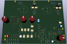
Working on designing boards to accommodate some capacitor changes on it. I needed to do this since the caps I want to use are too different in physical dimensions to work on my boards I picked up when they first hit the streets.
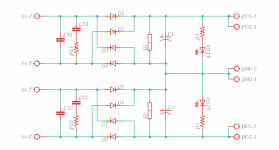
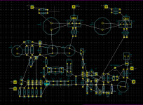
I have never used any schematic software before, so I am still getting used to it, but I do like this KiCad program. Furthermore, I have attached a few screenshots of where I am now. I still have some things to do as can be seen. I also need to see where TP1 ties in. I believe it is from the output of R17 to the wiper of P1, but I need to verify that.
I have never used any schematic software before, so I am still getting used to it, but I do like this KiCad program. Furthermore, I have attached a few screenshots of where I am now. I still have some things to do as can be seen. I also need to see where TP1 ties in. I believe it is from the output of R17 to the wiper of P1, but I need to verify that.
Attachments
Get the power supply components off the board.Working on designing boards to accommodate some capacitor changes on it.
Tighten the layout to keep ground connections compact.
Thank you for your thoughts.
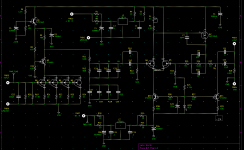
There are no power supply parts in there; basically I have Wayne's schematic and layout open in another window and laying out everything as he had them; so no PS parts.
Why I have you; do you feel the uTracer3+ would be a good enough device for someone using it for the tubes they own and then maybe a few more down the road or maybe wait for the 6? Thanks.
@exojam
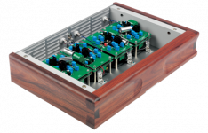
As an exercise (so far) I've taken a couple of circuits (not this one) and made layouts that separated signal circuitry from PSU distribution circuitry. The intent was to get a compact and straightforward signal layout without having to use unnecessarily-long traces to accommodate components. I did the layouts for stacked boards interconnected with short wire links or resistor links. Indeed, with one phono circuit I separated the passive components from the active ones from the PSU distribution.
I haven't implemented these yet... I'm trying to work up the courage to use a computer layout programme.
It wasn't the inspiration, but after the fact I realized that the Lyra Connoisseur Phono preamp was executed in a similar vein.
Attachments
Download KiCad and have some fun!
I had never used a PCB program myself until a few weeks ago. I wanted to change up a few things on the Pearl, so I said what the hell. It is a free program that works on Windows and Linux. Documentation is very good, active forum and lots of YouTube videos to help.
I only have about 10 hours on it, and I was able to put what I posted above together. Now with the suggestions from the gentleman above I am removing the voltage regulators and associated parts and making another board. The new board will hold those parts along with a power supply section. It is fun if you enjoy this type of stuff.
I do enjoy figuring out the layouts. I loved sticking down those GC donuts and Letraline on mylar to formalize my hand-drawn layouts (usually after many iterations). Making the boards was not a reliable process for me... part of why I guess I'll have to learn one of these programs so that I can get someone to make the boards.
I don't enjoy a computer program telling me how to do 'em or getting in the way of how I want to work. I had enough of that at work with AutoCad and Microsoft (anything).
I don't enjoy a computer program telling me how to do 'em or getting in the way of how I want to work. I had enough of that at work with AutoCad and Microsoft (anything).
- Home
- Amplifiers
- Pass Labs
- Building a Pearl 2