I am not sure about your comment about “program telling you how to do them”; but in my limited use of KiCad I find it super easy and allows you to do your thing.
Maybe some other KiCad users could chime in on it.
Maybe some other KiCad users could chime in on it.
You can build a nice tight, compact Pearl II "Manhattan Style" on PCB substrate with through-hole components.
Manhatten sounds about right especially with those tall caps!
My attempts have been "low rise"... both three stories.
The Leach phono stage was passives, actives and power distribution; a Marsh line stage (Pooge-3) was signal, servo and power distribution.
I might look at what a Pearl 2 would look like...
My attempts have been "low rise"... both three stories.
The Leach phono stage was passives, actives and power distribution; a Marsh line stage (Pooge-3) was signal, servo and power distribution.
I might look at what a Pearl 2 would look like...
You can build a nice tight, compact Pearl II "Manhattan Style" on PCB substrate with through-hole components.
Any thoughts on the utracer I asked you a few posts ago?
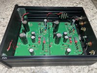
My finished Pearl II
Pretty much stock, no C7 or C15, R15 is a jumper. Stock Pass RIAA values.
R14 is 1K in series with a 220uF || 100nF. Probably a little hot gain wise for my Nagaoka MP-200 but I'm looking to move to MC very soon.
With no DC on the output I will be bypassing the output caps to see if I get any sonic improvements from that.
Very low floor noise as advertised!
Attachments
Last edited:
Thanks!!
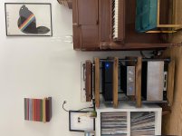
Forgot to attach a shot of the Pearl II in all her glory as part of my setup.
Pearl II - 12B4 linestage - F6 - Anthony Gallo Nucleus Reference 3.1
As space is tight and I wouldn’t be able to keep the PSU chassis far from the signal chassis the PSU transformer got put in a steel cover. Happy to report there is no audible noise at all. The transformer is as far away from the inputs as I could get them through the design of the chassis layout.
Attachments
Pass DIY Addict
Joined 2000
Paid Member
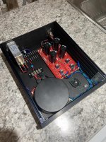
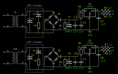
So as recommended to me, I took the power components off of the Pearl board and put them on the power supply board.
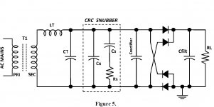
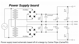
Now this board was based off of the CRC section from the Quasimodo, the LM3886 board and the power components of the Pearl 2.
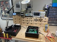
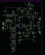
I have not a chance to finish everything in regards to this board and asking if anyone sees something wrong please correct me. I am also still trying to move everything on my Pearl board closer together but right now it is Bruins time.
James
Now this board was based off of the CRC section from the Quasimodo, the LM3886 board and the power components of the Pearl 2.
I have not a chance to finish everything in regards to this board and asking if anyone sees something wrong please correct me. I am also still trying to move everything on my Pearl board closer together but right now it is Bruins time.
James
Attachments
25v vs 35v 3300uf ?
Apologies if this is covered in an earlier response, but a quick search didn't find an answer.
Is there a reason the Mouser BOM link in the original post contains25v 3300uf caps instead of the 35v called for elsewhere?
Thanks for any assistance as I start on this build.
Apologies if this is covered in an earlier response, but a quick search didn't find an answer.
Is there a reason the Mouser BOM link in the original post contains25v 3300uf caps instead of the 35v called for elsewhere?
Thanks for any assistance as I start on this build.
Could have been a type-o as the Pearl 2 pdf shows it as a 35V cap.
I see what you are referring to as it is the link to Mouser where the cap(s) in question are located.
6L6 should be around soon for any clarification, but I would go with what is in the original pdf by Wayne.
I see what you are referring to as it is the link to Mouser where the cap(s) in question are located.
6L6 should be around soon for any clarification, but I would go with what is in the original pdf by Wayne.
Last edited:
Output Capacitor size and Film Capacitor Replacement
Hi
Just ordered the Pearl 2 boards and JFETS, so I've been looking over the circuit. Two questions and sorry if they've already been asked, but I can't find anything.
1. Why is out output cap so large (22uF)? I'll be putting the output into a preamp with a 50K input impedance. Even 2.2 uF should give me a -3dB cut-off frequency of a few Hz. I'm currently running a tube phono preamp amp with 1uF output capacitors and no loss of bottom end.
2. Anyone replaced the electrolytic output with a film capacitor (irrespective of the size)? Any comments on whether it improved the sound quality?
And (sorry a third question!), what are the dimensions of each board so I can look for some cases while waiting delivery.
Cheers and thanks
Vic_N
The 22 uF was a standard part in our stockroom at the time. A nice 1 uF of your favorite brand would be just fine.
And (sorry a third question!), what are the dimensions of each board so I can look for some cases while waiting delivery.
Vic_N
The boards are exactly 5" x 7"
The 22 uF was a standard part in our stockroom at the time. A nice 1 uF of your favorite brand would be just fine.
Hi Wayne
Thanks for the quick reply. I think I'll try a Mundorf Supreme. I find the sound from these as a coupling cap is very good for the price, possibly by-passed with a 0.01uf Russian teflon. We'll see. The silver oils I find tend to be a bit bright, but I have a spare pair, so may try these as well. The benefits and curse of DIY!🙂
Cheers
Vic
The boards are exactly 5" x 7"
Excellent! Thanks for the reply.
Cheers
Vic_N
The 22 uF was a standard part in our stockroom at the time. A nice 1 uF of your favorite brand would be just fine.
If anyone has any suggestions on improving the layout please let me know.
As Wayne said, you can change output caps for a smaller film one...
- Home
- Amplifiers
- Pass Labs
- Building a Pearl 2