Wayne was replying to someone else.
I was redesigning the board layout to take the power components off of the board and to also replace some caps with ones with larger footprint’s (which started this whole process for me). I am also doing this to learn the process of PCB design software.
I was redesigning the board layout to take the power components off of the board and to also replace some caps with ones with larger footprint’s (which started this whole process for me). I am also doing this to learn the process of PCB design software.
@exo
What board layout does that diagram produce?
How are you planning to organize the boards? Stack 'em? Side by side?
What board layout does that diagram produce?
How are you planning to organize the boards? Stack 'em? Side by side?
The board in post 2753 I had removed the power component’s and just had the circled component’s in the screenshot that is attached left on the board.
If I can get this verified that there are no issues with the layout; verify I have all components, grounds etc correct than I had planned on proceeding with the PCB. I am using KiCad so I would next need to do the netlist and than the component layout on the board and than gerber files made.
I was thinking a four layer board as jackinni had done for his very cool Pearl board.
Attachments
@exojam
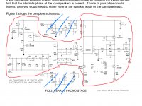
What you've shown in your post is the schematic.
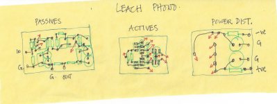
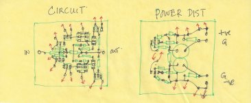
What I've been talking about is the board layout... where the components go and how the traces connect 'em. The design imperative was to get layouts that reflected the circuit design and used the shortest PCB traces.
Two examples:
With the Leach FET phono I separated passive from active devices onto two separate boards connected by short jumpers. Layered on top of those boards would be the power distribution board.
For the Marsh Pooge-3 linestage I separated out the active circuit from the power distribution and constant current sources. Marsh specified axial integrated units that matched the resistors that in places connected the +/- power to the circuit.
In both the red arrows indicate connections between boards.
What you've shown in your post is the schematic.
What I've been talking about is the board layout... where the components go and how the traces connect 'em. The design imperative was to get layouts that reflected the circuit design and used the shortest PCB traces.
Two examples:
With the Leach FET phono I separated passive from active devices onto two separate boards connected by short jumpers. Layered on top of those boards would be the power distribution board.
For the Marsh Pooge-3 linestage I separated out the active circuit from the power distribution and constant current sources. Marsh specified axial integrated units that matched the resistors that in places connected the +/- power to the circuit.
In both the red arrows indicate connections between boards.
Attachments
My apologies on that, I have not finished the board placement as of yet due to removing the power section from the main board.
Once I finish up I will be more than happy to post them since I will probably make some mistakes and will be looking for someone to point it out. Since this is my first time doing this process is the reason why feel there might be/ will be something I do incorrectly.
Also I do not believe I will go as far as to separate active and passive devices onto two separate boards. I am just planning to do a power and a main board.
Last edited:
The separation fell out of the way the short trace study turned out.
On the Pearl, my first impression is that Wayne's layout after the RIAA is good. I was playing with the possibilities of moving Q3 to line up with the input FETs and integrating the FET ground with the RIAA ground... Make all those components attach to the same short trace. It's just an idea.
On the Pearl, my first impression is that Wayne's layout after the RIAA is good. I was playing with the possibilities of moving Q3 to line up with the input FETs and integrating the FET ground with the RIAA ground... Make all those components attach to the same short trace. It's just an idea.
Give me a little time and I will try and take your schematic’s and build up some boards in KiCad.
What trace width is what we would be looking for? I am sure I will have some questions like that once I get to that point in the process.
What trace width is what we would be looking for? I am sure I will have some questions like that once I get to that point in the process.
Oh, I didn't post these to get you to lay out boards. I have to do that myself. And I'm still playing...
They're just food for thought... grist.
They're just food for thought... grist.
Last edited:
MC carts
I have an AT33EV cartridge with has 10 ohm impedance. I am confused as to:
1. R20 = 100ohm and keep R19= 47k
2. Remove R19
I have an AT33EV cartridge with has 10 ohm impedance. I am confused as to:
1. R20 = 100ohm and keep R19= 47k
2. Remove R19
I would add R20=100ohm which would give a load impedance of about ~100ohm which is what is recommended for the AT33EV.
This way, if you ever switch to MM you only need to remove 1 resistor instead of removing 1 and adding 1.
Alternatively, you could wire the 100ohm resistor to R20 with a switch so that you can toggle between MM/MC (47.5K/100).
This way, if you ever switch to MM you only need to remove 1 resistor instead of removing 1 and adding 1.
Alternatively, you could wire the 100ohm resistor to R20 with a switch so that you can toggle between MM/MC (47.5K/100).
Changing resistor values
Changed R14 from 450 ohms to 660 ohms, this has reduced the hum at high volume which was getting very frustrating.
Changed R14 from 450 ohms to 660 ohms, this has reduced the hum at high volume which was getting very frustrating.
R15 + R16 form a voltage divider with R14 that generates the feedback for the second gain stage. Normally R15 is a shorted (0R), but of you add a resistor there it reduces the feedback and thereby increases the gain. For example, put a 215k resistor there gives a 10dB increase in gain.
Cheers,
Terry
Cheers,
Terry
R15 + R16 form a voltage divider with R14 that generates the feedback for the second gain stage. Normally R15 is a shorted (0R), but of you add a resistor there it reduces the feedback and thereby increases the gain. For example, put a 215k resistor there gives a 10dB increase in gain.
Cheers,
Terry
Nice clear explanation. I also agree with careers invading audio time.😀
Russellc
Hi
I've put together a little Excel spreadsheet to calculate the gain on the Pearl 2 based on what I've managed to glean from this forum. If someone could double check the calculations, that would be great. Hopefully it can help people work out what resistor values to put in R14, 15 and 16.
It lets you put in the mV output for your cartridge and determine the gain required to get a 1V output from the Pearl amp. I've put in 2 cartridge already, the Grace F9 that I'm running (MM) and a very low output cartridge, the Denon103R (MC). You can then play around with the resistor values and get the gain you need. I've put in the resistor values I'll use to get desired gain for my F9.
Your can download it from the following Google Drive link:
Peral 2 Gain Calculator.xlsx - Google Drive
Cheers
Vic

finally
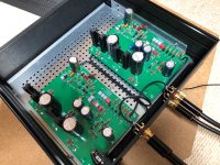
I have been working on the amplifier again for two months and finally came across the solution.
At first I tried a few tips from you, but this did not solve my problem with "motorboating".
I read a lot about this problem and then came to the conclusion that either the capacitors, the transformer or something with the shielding had to do with it.
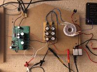
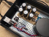
The next step was to rebuild the power supply.
Ordered new parts straight away and put the whole thing together on a perfboard. It was still there ...
New transformer connected. It was still there ...
No matter what I did, it just wouldn't go away. In addition, one channel no longer worked.
I ordered new parts again and luckily I was able to repair the channel. yay!
Since the problem continued to haunt me and I already had sleepless nights because of it, I had to approach it from a new perspective.
I disassembled the whole amplifier, desperately measured and checked everything. While playing around I suddenly saw it (motorboating) on my multimeter!
I started to measure my whole apartment to see if it had an origin, but to no avail. anyway, I finally saw it.
The whole amplifier was put back together. Went to my dad to connect it to his system and lo and behold, it was gone.
What a relief!
tl;dr
Amplifier works, it's the apartment.
Time to move to another thread – ba3 preamp (and physically to another place).
The next challenge can begin.
Thanks everyone
Jules
I have been working on the amplifier again for two months and finally came across the solution.
At first I tried a few tips from you, but this did not solve my problem with "motorboating".
I read a lot about this problem and then came to the conclusion that either the capacitors, the transformer or something with the shielding had to do with it.
The next step was to rebuild the power supply.
Ordered new parts straight away and put the whole thing together on a perfboard. It was still there ...
New transformer connected. It was still there ...
No matter what I did, it just wouldn't go away. In addition, one channel no longer worked.
I ordered new parts again and luckily I was able to repair the channel. yay!
Since the problem continued to haunt me and I already had sleepless nights because of it, I had to approach it from a new perspective.
I disassembled the whole amplifier, desperately measured and checked everything. While playing around I suddenly saw it (motorboating) on my multimeter!
I started to measure my whole apartment to see if it had an origin, but to no avail. anyway, I finally saw it.
The whole amplifier was put back together. Went to my dad to connect it to his system and lo and behold, it was gone.
What a relief!
tl;dr
Amplifier works, it's the apartment.
Time to move to another thread – ba3 preamp (and physically to another place).
The next challenge can begin.
Thanks everyone
Jules
Attachments
- Home
- Amplifiers
- Pass Labs
- Building a Pearl 2