Hi Allen
Just a quick one, getting things ready and getting a plane 2morrow morning.
With the 'receiving' speaker there is a nice sine wave (2KHz) when the speakers are an exact distance apart. I get something like 500mV on True RMS meter. I then connect it to a 1R resistor across speaker terminals and I still get the sine wave on scope, but reduced amplitude as expected. I then connect it to the output of an amplifier (with shortened input) via 1R on the ground side. This amp is TDA2030 based chip amp, very low output Z. The sine wave is still there at the same level, but I tell you it does not look clean. This is interesting as it should look the same in theory but there is visible distortion. When I get back, that will be my starting point as I can put the result through the audio analyser because I have visible distortion. This means that there is some reaction on the part of the amplifier or else I would have something that would look almost pure sine, but I am not. The amp is producing 0V, so this is current on the current side of the amplifier. What if another amplifier of a different type, like a tube amp or a Class D amp etc, what if that changes with the amp? Will that distorted sine wave change, be better or worse. What numbers will the analyser come up with.
What if we hear better sound from the amps that are better behaved in this respect, then we have correlation and that should open the field to further explore. Let us see,
But so far so good.
Next stop, Singapore, and yes I will be able to read emails etc.
Cheers, Joe
In that case you might be interested in this thread - https://www.diyaudio.com/community/...ce-wasnt-complete-what-are-we-missing.398934/
^^ Hi,
Are you using another speaker as microphone? And explaining that you have setup where you short the "mic" with a resistor from which you use to sense current? When there is no amplifier connected on the circuit it seems clean, but when you hookup an amplifier in series as well without any input to it, just idling around, then you would measure (see) some distortion over the resistor?
Yeah if it was ideal amplifier, there shouldn't be any difference and the output should just look like a resistance in series. If there is distortion its not. Sweep around with the frequency and see where the distortion is, if it correlates for the "mic" loudspeaker impedance and its phase angle for example. Or something else.
Reasoning, reading about EPDR, Equivalent Peak Dissipation Resistance, which kind of shows actual load impedance for class B amplifier, how much power turns into heat. Here is an example. Nominal ~4ohm speaker, but the reactive load lowers the impedance worst case to about 2ohms, which would require quite lot of current capability from the amplifier.

Now 8ohms parallel resistor added to the speaker the impedance plot is smoother, and max phase angle is less but the EDPR is even lower now requiring even more current from the amplifier than before.

Now if we assume perception of better sound with parallel resistor and reason about it: Since current demand from the amplifier got up, not down, the better sound quality must not be from the "ability to deliver current" as aggregate total but from the phase angle for example, which somehow affects how the amplifier works. It might be also that distortion went up, and it sounds better 🙂
If assuming its a class D amp who seem to have less distortion with higher output voltage. This would provide another way to reduce distortion by adding a series resistor, which would increase amplifier voltage output for same current. This would allow increase the parallel resistor while keeping the phase angles the same. Here with 30ohm parallel resistor and 4ohm series resistor. Much easier load for the amp I thinks. But, less headroom of course, we now have amplifier voltage and current up and acoustic output down. Peaking bass response etc. Well, something to think about.

Are you using another speaker as microphone? And explaining that you have setup where you short the "mic" with a resistor from which you use to sense current? When there is no amplifier connected on the circuit it seems clean, but when you hookup an amplifier in series as well without any input to it, just idling around, then you would measure (see) some distortion over the resistor?
Yeah if it was ideal amplifier, there shouldn't be any difference and the output should just look like a resistance in series. If there is distortion its not. Sweep around with the frequency and see where the distortion is, if it correlates for the "mic" loudspeaker impedance and its phase angle for example. Or something else.
Reasoning, reading about EPDR, Equivalent Peak Dissipation Resistance, which kind of shows actual load impedance for class B amplifier, how much power turns into heat. Here is an example. Nominal ~4ohm speaker, but the reactive load lowers the impedance worst case to about 2ohms, which would require quite lot of current capability from the amplifier.
Now 8ohms parallel resistor added to the speaker the impedance plot is smoother, and max phase angle is less but the EDPR is even lower now requiring even more current from the amplifier than before.
Now if we assume perception of better sound with parallel resistor and reason about it: Since current demand from the amplifier got up, not down, the better sound quality must not be from the "ability to deliver current" as aggregate total but from the phase angle for example, which somehow affects how the amplifier works. It might be also that distortion went up, and it sounds better 🙂
If assuming its a class D amp who seem to have less distortion with higher output voltage. This would provide another way to reduce distortion by adding a series resistor, which would increase amplifier voltage output for same current. This would allow increase the parallel resistor while keeping the phase angles the same. Here with 30ohm parallel resistor and 4ohm series resistor. Much easier load for the amp I thinks. But, less headroom of course, we now have amplifier voltage and current up and acoustic output down. Peaking bass response etc. Well, something to think about.
Last edited:
Very recently fellow diyaudio member KSTR on the other forum mentions that output impedance is not stable but modulated by load current. I have no idea if this is for all amplifiers or just some. If you see hash on top of sine on the circuit with amplifier output in series, it could be explained by the output impedance being modulated. Following posts on the thread linked explain how to test it, inject current directly.When I get back, that will be my starting point as I can put the result through the audio analyser because I have visible distortion. This means that there is some reaction on the part of the amplifier or else I would have something that would look almost pure sine, but I am not. The amp is producing 0V, so this is current on the current side of the amplifier.
ps. interesting side thought: if you are having two speaker setup so that the other works as a mic, and see pristine sine wave on scope when the mic speaker is shorted, it means there is no distortion (or relatively less than with the amplifier output modulation) on the speaker that outputs the sound. Or, it might be so that if the speakers are opposing each other they move to opposite directions perhaps cancelling out some distortion 😉 Anyway, I think the results indicate the amplifier distortion is greater than driver distortion.
Last edited:
Hello All,Just a quick one, getting things ready and getting a plane 2morrow morning.
A quick reply.
What are the limits of the TDA2030 chip amplifier? A likely place to start. Go to the datasheet and search limit.
14 Watts at 0.5% distortion.
Hard thermal overload distortion, typical of a chip amplifier.
"Output peak current internally limited" at 3.5Amps. For the example of 2000Hz the output is limited to 3.5 +- Amps. That sounds like hard symmetrical clipping at 2000Hz and the entire family of odd Harmonics to go with it.
There is no need for a long drawn out discussion of the theory.
Thanks DT

Thanks for posting this, Joe, I have tried this idea for Back EMF suppression. On my system, as discussed, I have attached the resistors to the output terminals of the amplifier that you upgraded. The results are chalk and cheese in comparison in relation to the sound quality. And the measured current phase angle improved too, which was a nice confirmation. I'm a new member, I'm posting on this thread, we can talk when you get back.
A tiny digression, my Elsinores turned 3 last month. I have to say im so very happy i dove in. The detail these magnificent speakers provide is always so intriguing. I hear something for the first time almost every time i actually have time to sit and truly listen... Almost every listening session leaves me in awe. My 300B finally dialed in (for now lol!) and my 2 girlfriends (according to my wife) provide goose bumbs and yes even tears. Thanks so very much Joe, for all you have done and continue to do!
AudioFanMan,
Good to know that you have been enjoying the music. 🙂
Any pictures of the speakers/your setup that you would like to share?
Good to know that you have been enjoying the music. 🙂
Any pictures of the speakers/your setup that you would like to share?
Back from my break. Singapore, humid but weather was good and no rain... and it's an expensive place.
The "NBAC" back version should be realised over the next few months. Will it be official Elsinore version? That remains to be seen. The output is likely around -1.5dB relative to "MFC" and Purifi "ULD" version, which are both pretty much the same. But the "NBAC" will still be an incredibly easy speaker to drive.
As shown below, Elsinores can even be used with the few Watts of a 300B amp.
Thanks, a post like this makes me realise the effort was worth it. Spreading a bit of happiness is happiness in itself - paraphrasing JC, if you know what I mean.
The "NBAC" back version should be realised over the next few months. Will it be official Elsinore version? That remains to be seen. The output is likely around -1.5dB relative to "MFC" and Purifi "ULD" version, which are both pretty much the same. But the "NBAC" will still be an incredibly easy speaker to drive.
As shown below, Elsinores can even be used with the few Watts of a 300B amp.
A tiny digression, my Elsinores turned 3 last month. I have to say im so very happy i dove in. The detail these magnificent speakers provide is always so intriguing. I hear something for the first time almost every time i actually have time to sit and truly listen... Almost every listening session leaves me in awe. My 300B finally dialed in...
Thanks, a post like this makes me realise the effort was worth it. Spreading a bit of happiness is happiness in itself - paraphrasing JC, if you know what I mean.
Joe, maybe the new Purifi tweeter seen in this article could be a valid upgrade in the ULD-version? Built in waveguide with awesome dispersion and if I'm not mistaken a very healthy xmax suitable for low order crossovers. 🙂
https://purifi-audio.com/blog/tech-notes-1/spk16-reference-design-12
https://purifi-audio.com/blog/tech-notes-1/spk16-reference-design-12
Yep, this has been a long time coming and many of us has been waiting to see what comes out of it. There are things that I can't yet see re the design of the Purifi tweeter yet. Will it be 6-8 Ohm and well above 90dB sensitivity? We know it will be long-throw (X-Max) and that is certainly desirable. But I have to tell you, knowing how things like that works, a long voice coil outside the magnetic gap will have a penalty in the form of lower sensitivity and that could be a problem with the high system sensitivity of the Elsinores. But we shall see what comes out. Maybe a very strong magnetic system can over come that? Has anybody seen something that I haven't?
AudioFanMan,
Good to know that you have been enjoying the music. 🙂
Any pictures of the speakers/your setup that you would like to share?
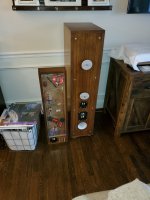
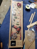
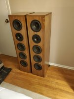
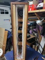
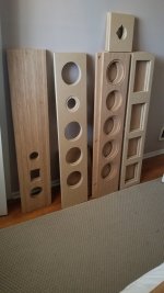
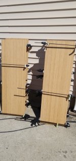
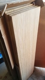
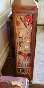
Few build pics attached...
Sorry for the delay....
The only thing worse than tearing a laptop apart is putting it back together!
My "fun" laptop, retired from active duty in 2014... Bought in 2009, still going!
Attachments
-
 5.75 1024-1365.jpg267.1 KB · Views: 171
 -
 5.5 1024-1365.jpg422.9 KB · Views: 186
 -
 5 -1024-1365.jpg238.2 KB · Views: 189
 -
 4.5 1024-1365.jpg313.3 KB · Views: 180
 -
 4 -20200411_100359.jpg219.9 KB · Views: 160
 -
 3- 20200404_172844.jpg396.5 KB · Views: 174
 -
 2- 20200327_171859.jpg282.2 KB · Views: 159
 -
 1.5 Attach30284_20200315_140338.jpg285.8 KB · Views: 163
 -
 1- 1024-1820.jpg331.4 KB · Views: 166
 -
 6- aa.jpg304.5 KB · Views: 171
Just indicated via Lars over on the Purifi build thread “tweeter in the spk16 WG is around 95dB at 2kHz”Yep, this has been a long time coming and many of us has been waiting to see what comes out of it. There are things that I can't yet see re the design of the Purifi tweeter yet. Will it be 6-8 Ohm and well above 90dB sensitivity? We know it will be long-throw (X-Max) and that is certainly desirable. But I have to tell you, knowing how things like that works, a long voice coil outside the magnetic gap will have a penalty in the form of lower sensitivity and that could be a problem with the high system sensitivity of the Elsinores. But we shall see what comes out. Maybe a very strong magnetic system can over come that? Has anybody seen something that I haven't?
So hopefully suitable for Elsinore
This is the Revel M126Be and it sells for AUD $7500, so it is a premium compact speaker with 6" driver and Beryllium tweeter.
View attachment 1170674
Rear:
View attachment 1170675
Nicely made speaker, as you would expect for the price.
Now this is where some parallel 8R 100W resistors were added and the two Z responses below:
View attachment 1170678
We can see that through the critical mid-frequencies how flat it looks. At those frequencies there is a lot more current going through the parallel resistor, I did a quick calculation, About 71% goes through the resistor at 2KHz and 29% on to the crossover and on to the drivers. The amplifier sees more of the resistor than the speakers, particularly around the crossover point. Is this having a stabilising affect around the crossover. Yes, saying stable may not be the best word, but is is what comes to mind.
Let us look to the current phase angle:
View attachment 1170673
We can see that above 1KHz the phase angle is under 10° deviation from zero degrees.
Of course this all looks very academic... until you listen to it. The difference in sound is not hard to spot and this neat trick, usually with 2-Way speakers like this, it has now been done so many times.
So we have a mystery on our hands.
Personally I think that they way that current behaves has to be a key, this what has to lead to an answer. I am running experiments where you can have the current of the amplifier look very different from the voltage. What is interesting, the closer that we get to a resistor and when we get to using an actual resistor, only then does the voltage and the current look the same. But what good is that, we don't listen to resistors.
My suggestion is that we use amplifiers to test speakers, but we need speakers to test amplifiers. That is the challenge.
As a post script, adding the 8R in series also leads to am improvement. But here you will hear a slightly more mid presence and fuller bass, but also a bit more pure sounding. When we add 8R series resistance, we also get a flatter current phase angle. So it against points to current as being at the heart of this and hence figuring out why.
In the meantime, if you know anybody with a typical 2-Way speaker system that is rated at 8 Ohm and you have some spare 8R resistors lying around (you can get sandcast 8R2 just about anywhere), get them to try it. It is likely they will like it and leave those resistors in place and just enjoy and forget.
Packing and going to Singapore for a break.
PS: The above are actual measurements of the speaker, thank you to Isaac for bringing them around. Isaac follows things here.
Hello,
With the M126Be and test equipment sitting right there on the shelf run a couple of Log sweeps and show us the HD and IMD results with and without the parallel resistor.
Thanks DT
I don't have the M126Be here, I had it for a few minutes. But I am working on a measurement that looks at this from an angle that is quite different.
Just indicated via Lars over on the Purifi build thread “tweeter in the spk16 WG is around 95dB at 2kHz”
So hopefully suitable for Elsinore
Thank you.
But is it 4-6-8 Ohm? I imagine the resonance will be a low 500-700Hz. The responses on/off axis, will they show that classic waveguide 'gain' where the response below 10KHz rises to hopefully by 5dB typically around 3KHz. So the response should not be flat. For example, if it gets to around 95dB @ 3KHz and only 90dB @ 8-10KHz, then 95dB might not be quite enough because we have to be guided by what happens at 10KHz?
So there are still things to be revealed. I am sure we shall get all that in time. And they are releasing more than one Waveguide and also that there seems to be a modular approach. It will all be very interesting.
We can see that through the critical mid-frequencies how flat it looks. At those frequencies there is a lot more current going through the parallel resistor, I did a quick calculation, About 71% goes through the resistor at 2KHz and 29% on to the crossover and on to the drivers. The amplifier sees more of the resistor than the speakers, particularly around the crossover point. Is this having a stabilising affect around the crossover. Yes, saying stable may not be the best word, but is is what comes to mind.
The output of the speaker is determined only by the voltage and current going through the speaker. As long as the amplifier is able to supply both the speaker and the parallel resistor the speaker output will remain unchanged. My measurements with a sensing resistor placed in series with only the speaker demonstrate this.
Thanks DT
Indeed.. and the current phase angle through the speaker can be (and typically is) different to that through the resistor.The output of the speaker is determined only by the voltage and current going through the speaker.
- Home
- Loudspeakers
- Multi-Way
- The "Elsinore Project" Thread