Great progress! When you get to listening again, read some XO tweaking advice Introduction to designing crossovers without measurement
It looks like you're taking some measurements. That's neat!
If you take normal measurements in-room, with the mic at your listening position, you will measure the speaker, and also the room. Especially in the bass, room effects can make it difficult to tell what the speaker is doing.
A "ground plane" measurement is the easiest way to get around this. You put the mic on the ground, so there is effectively no reflection from it. If you leave the speaker in the normal position you will not capture the on-axis upper frequency information, and only get bass performance. If you can point the listening axis at the mic while it is on the ground you can capture information to a higher frequency. It might be best to do this with the speaker on its side or upside down, to bring the HF axis closer to the mic.
If you can manage to do this outside in an open space (on a hard surface) you can get reflection free data over a wide bandwidth. That's helpful for crossover evaluation. You can still set a window in REW to exclude reflections.
If you go in REW to the "controls" button (gear, on the right side, by the graph) and select "generate minimum phase" The software will clean up your phase data somewhat.
You can generate your own FRD measurements this way. If you do so, you can measure how to set up the correct driver delay in XSim. Take a measurement of the tweeter, then a measurement of the woofer, and then a measurement of them both together, all without moving the mic or speaker. (Be careful to limit the bandwidth of your tweeter measurements, so you don't damage your drivers!) When you measure the two drivers together, you should see the interference pattern they make with each other. Load the individual driver measurements in XSim and wire them both up so XSim is showing the effect of both drivers. Then in the graph, load the measurement of both drivers together as a curve from file. Then adjust the driver delays until XSim's simulation matches the reality you measured.
This way you can use XSim to design based on your own measurements.
Welcome AdamThorne
motokok i have read https://www.diyaudio.com/forums/mul...ing-crossovers-measurement-2.html#post2587247
But don´t know what to do.
I havent got any resistors in the xover for tweeter, the woofer only have a big 10mH coil and a 305uF cap (i change it from 205uF with a electrolyt 100uF)
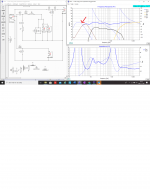
Seams to me there is some problem in the xover from 350 hz and down, as some of the xover-parts seems to "quarrel a little", and the "knee" down around 350 hz is problematic i think ( also seen in phase-curve from xover-point 150hz)
And the arrow i draw in the pic Xsim211104, why the curve don´t go up ?, it goes up a bit but then it turns down again ??....The other 2 curves goes up pretty in a waveform.
AdamThorne:
These measaurements are from mic on the floor, with no and more damping around the mic.
And i have spend a lot of time in XSim to try get the 350hz knee away, but i don´t make any progress.
So i post you guy´s the hole FRD, ZMA, Xsim files in here with the latest info.
Regards John
motokok i have read https://www.diyaudio.com/forums/mul...ing-crossovers-measurement-2.html#post2587247
But don´t know what to do.
I havent got any resistors in the xover for tweeter, the woofer only have a big 10mH coil and a 305uF cap (i change it from 205uF with a electrolyt 100uF)
Seams to me there is some problem in the xover from 350 hz and down, as some of the xover-parts seems to "quarrel a little", and the "knee" down around 350 hz is problematic i think ( also seen in phase-curve from xover-point 150hz)
And the arrow i draw in the pic Xsim211104, why the curve don´t go up ?, it goes up a bit but then it turns down again ??....The other 2 curves goes up pretty in a waveform.
AdamThorne:
These measaurements are from mic on the floor, with no and more damping around the mic.
And i have spend a lot of time in XSim to try get the 350hz knee away, but i don´t make any progress.
So i post you guy´s the hole FRD, ZMA, Xsim files in here with the latest info.
Regards John
Attachments
AdamThorne
Smart to use own measauremnets, can i do that even with 1 speaker + (because the other one has old xover and orginal port and no damping)
Just put mic in the sofa where i use to sit and measaure?.
Have problems with REW also, it crasch from time to time saying "java.lang.ArrayIndexOutOfBoundsException 1417"
Try to find Java config for language without success
Regards John
John, could you take new driver measurements in cabinet with no crossover?
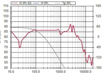
I think you're seeing the reality of the baffle and box vs the datasheet response from an infinite baffle and anechoic chamber. For example, this is the response of the woofer at the moment vs your target curve. Either the measurement is way off or the response shows the current XO is not working anywhere near intentions.
I think you're seeing the reality of the baffle and box vs the datasheet response from an infinite baffle and anechoic chamber. For example, this is the response of the woofer at the moment vs your target curve. Either the measurement is way off or the response shows the current XO is not working anywhere near intentions.
Attachments
Hi Jawen,
The new measurements you posted are with the microphone at the position of your ears when seated at the sofa, and the amp volume control set to the same position for all tests ?
If you kept the microphone in that exact position when you measured each individual driver you should have frequency with the relative phase data that should allow Xsim to work well.
The 350Hz knee you mention maybe a result of the two mids or diffraction problem or less than optimum phase information. Interesting that you do not see a 350Hz bump with the Xover in the other speaker.
A quick test to see if you can change the 350Hz knee is to try it with the woofer reversed. It should highlight it is phase related if it changes with the woofer reversed.
Its a very subtle one, but you are using the same FRD and ZMA info for both 5" faitals. I am quite happy that the impedance should be the same but there probably will be a small change in the frequency response between the two positions. For the time being I think it is a minor issue and would need more time for further measurement to clarify.
Ground plane measurements seem to give excellent results, but I think they ideally need a hard fixed surface, and lots of free space to stop reflections form fences, walls and such muddying the results. Definitely worth reading up on if you have plenty of free space do do them in. I have never attempted one so cannot give any advice. Envious of those who have the space.
NB on the sim I have posted the Bass is opposite phase to the other drivers. There is also a bit more simplification.
Attachments
Last edited:
,
I would try to keep it simple for the time being and set the microphone up at 1 metre distance at a height that would normally match where your ears would be relative to the speaker. Usually this should be somewhere near to the centreline of the tweeter on a large floor standing speaker.
Capturing a good approximation of the bass is going to take a bit more time. We should be able to get the mid and tweeter working well quickly, if the data is good.
I know form previous experience with the tweeter that is a workable selection of values.
Yes, please take the measurements without the crossovers that will give us real data to work with keep the microphone in one postion and the volume the same, not too loud as you do not want to damage the tweeter, Some people use a couple of uF in series to protect it.
Last edited:
raymondj:
The post 74 is from listeningposition in sofa, all others ( posting 75, 77, 79, 80 and 83) from 1 m in the middle of the MTM !
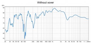
Done measuremant without xover.....Look´s crappy and i need a whiskey.
The Jamo´s are cheep right now if someone suddenly knocked on my door hahaha
Witout xover from 1 m
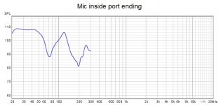
And inside ending of port with xover
Regards John
The post 74 is from listeningposition in sofa, all others ( posting 75, 77, 79, 80 and 83) from 1 m in the middle of the MTM !
Done measuremant without xover.....Look´s crappy and i need a whiskey.
The Jamo´s are cheep right now if someone suddenly knocked on my door hahaha
Witout xover from 1 m
And inside ending of port with xover
Regards John
Attachments
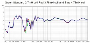
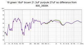
Eariler i have done some testing, i test 3 different values on coil in paralell with cap in the mid´s.
Some differences in 100to 200 hz zone as shown.
I also test 3 different values on cap`s in paralell with coil in the mid´s.
Some differens in the 1800-3000 hz area.
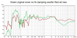
And pic´s from 1 m on both speaker, one with orginal xover and "new" xover.
Regards John
Some differences in 100to 200 hz zone as shown.
I also test 3 different values on cap`s in paralell with coil in the mid´s.
Some differens in the 1800-3000 hz area.
And pic´s from 1 m on both speaker, one with orginal xover and "new" xover.
Regards John
Attachments
Sorry motokok i read wrong and my head is spinning, it was you telling me to measure without xover !
Good idea!
raymond:
I had look at you latest xover in XSim, and i think i have all exept the 10uF cap and if i can use old elektrolytcaps i probually have for the big 360uF also.
Is Electrolyt from Philips from 1992 okey to test with ?
Regards John
Good idea!
raymond:
I had look at you latest xover in XSim, and i think i have all exept the 10uF cap and if i can use old elektrolytcaps i probually have for the big 360uF also.
Is Electrolyt from Philips from 1992 okey to test with ?
Regards John
Measurement without crossover will look crappy.
But they will show baffle step effect on midrange and tweeter along with the corresponding phase which is needed to get optimum results.
The low frequency of the mid and woofer will have room modes ( possibly the dips at 200Hz and 100Hz that you are measuring) effecting them which potentially spoils the data. That's why we ideally need the big non reflective empty space or ground plane measurement to give us that clean data.
You have probably read about placing the microphone as near as possible to the cone and taking a measurement in that position and then intelligently splicing onto the quasi anechoic data to give a better representation of the low frequency performance.
Your Bass speaker is at the bottom of the enclosure with a port on the rear of the speaker that makes it tricky to do by scaling measurements so that may end up as a judgement call and adjusting port lengths and enclosure stuffing.
I have reconsidered the capacitor, I think i was being over cautious, use the tweeter directly connected. Just start with the amp volume at zero and gently increase it so that you have 80dbs or thereabouts as the level. The frequency chirp is so short lived that it should not be an issue at sensible measurement levels. You use the term electrolytic, The larger value audio caps are Non Polarised (NP) types specifically for audio I wouldn't use an electrolytic for any loudspeaker crossover
Last edited:
Hi Jawen,
Looking back at the data you mentioned plus the data in post 90 suggest you are getting close. The red graph in post 90 your crossover and the new drivers isn't far from the mark. You just need to refine the interaction of the 2 mids and tweeters. Interestingly what did you think to the sound?
As post 90 looks sensible to me, maybe this crossover and the new measurements of drivers without Xover in box will be a good restarting point. You just need to flatten that 2Khz bump. Lets concentrate on that as a starter.
Looking at the posted data all have issues caused by the room from 300Hz downwards.
Its not your measurements we all have the same issue taking measurements in our homes.
I usually have a huge response dropout somewhere around 200Hz or so. You have 100Hz, 200Hz and 300Hz re occurring in your measurements which makes the low slightly more difficult to judge.
When you are happy to re visit this, and once you have new responses and impedances for the drivers measured. Simply, forget about the bass for now and see if you can get a smoother response between 300Hz-15Khz. with a lovely roll on from 100 - 300Hz which is where your room seems to get involved. But we should try for this and from the Xsim data knowing the crossover roll on we should be able to integrate the bass back into the system using a complimentary roll off on the bass driver.
Variation in the measurements below 2 dBs and general flatness are the things to aim for.. Don't worry too much about dips, you will never easily achieve the flatness of a simulation and it can be counter productive.
Post 75, the brown old Xover dips at 100Hz, 200 and 300. 400hz -2K looks promising.
Post 77, Pink looks sensible, i think it also shows the difference in the woofer sensitivity and hence the need to probably attenuate the mid and tweeter level. 2K bump needs understanding. I.e. is it mid and tweeter crossover phasing and adjustment of components. Ideally balancing mid and tweeter to lessen this, will probably end up with a small dip after tuning. Tune by 1 component change at a time to get a feel for interaction, alternate between the mid an tweeter as you change 1 value and see the interaction. The more you do this and take measurements the the more proficient you become.
Post 79 also shows mid and tweeter higher efficiency. Re adjust Xover for smoother 2000 -3000Hz
Post 80, looks OK.
Post 83, 100Hz dip, generally quite confusing.
Maybe if you are having time away from this, you can search the internet and do some reading. Somewhere on the audiomatica website there are some words about measurement of loudspeakers as a download.
Also have a look at the Loudsoft webpage and FINE X crossover videos and downloads.
Same goes for studying VituixCad info and videos
I am sure others will post their recommendations for useful reading.
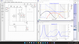
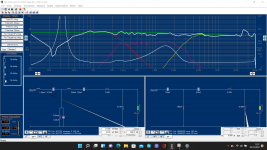
In a simulation these two components allow you to play with things relatively easily and yet make large swings.
If you wanted to you could drop these values into Xsim and work from there. This is to give you a dial that you can adjust that should bring on quick changes, have a play.
The arrows in the attachment indicate the two primary components to adjust. Once you can prove it is behaving as per the model, the parallel inductor on the midrange will effect the roll on knee which you may also need.
Attachments
Thank you very much for the dedicated answer raymondj ")
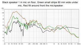
About post 83, the microfone was on the floor about 25cm from the speaker!.
Black curve all hard woodfloor, Green curve after ivé put a 12cm wide stripe from mic going under the woofer and to the back of the speaker.
And Red curve after i put polyestersheets all around (nearest) speaker.
Because caps are so expensive, i dont have so many different values at home to try out the xover, i have 3,3, 12, 15, 18 to work with at the moment.
Resistors ihave a lot from 1-5,6 Ohm and also some 15 ohm.
Colis i have from 0,48-6 mH, and also have "skills" to make my own value with take of or put more wire o it and measaure with my LCR-meter....even with a ironbult inside i can get values over 10 mH.
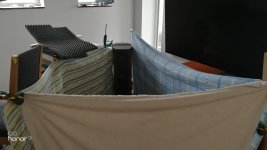
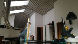
Today i have try to make a echofree invirement around the speaker and mic around the "ordenary" measaure-space, and i have 10-15mm blankets/filt/carpet all around the speaker and microfone up to 15 cm over the top of the speaker.
And did mesaurements on hole speaker without xover AND, only tweeter, only midrange, and only woofer also without xover.
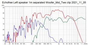
One pic is from hole speaker connected, the other put together from separate twe/mid/woofer measaurements in 1 curve, and also the twe, mid, and woofer separate measaurements.
The tweeter and midrange mesaurments should be much more non-affected by the room.
Forgot to tell you what i think the speaker sounds like at the time.
Bass strong and quite nice, quite fun to listen to and even delivers emotions
Regards John
About post 83, the microfone was on the floor about 25cm from the speaker!.
Black curve all hard woodfloor, Green curve after ivé put a 12cm wide stripe from mic going under the woofer and to the back of the speaker.
And Red curve after i put polyestersheets all around (nearest) speaker.
Because caps are so expensive, i dont have so many different values at home to try out the xover, i have 3,3, 12, 15, 18 to work with at the moment.
Resistors ihave a lot from 1-5,6 Ohm and also some 15 ohm.
Colis i have from 0,48-6 mH, and also have "skills" to make my own value with take of or put more wire o it and measaure with my LCR-meter....even with a ironbult inside i can get values over 10 mH.
Today i have try to make a echofree invirement around the speaker and mic around the "ordenary" measaure-space, and i have 10-15mm blankets/filt/carpet all around the speaker and microfone up to 15 cm over the top of the speaker.
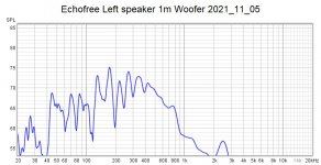
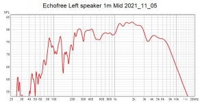
And did mesaurements on hole speaker without xover AND, only tweeter, only midrange, and only woofer also without xover.
One pic is from hole speaker connected, the other put together from separate twe/mid/woofer measaurements in 1 curve, and also the twe, mid, and woofer separate measaurements.
The tweeter and midrange mesaurments should be much more non-affected by the room.
Forgot to tell you what i think the speaker sounds like at the time.
Bass strong and quite nice, quite fun to listen to and even delivers emotions
Regards John
Attachments
-
 IMG_20211105_113805.jpg336.2 KB · Views: 107
 -
 IMG_20211105_112218.jpg394.6 KB · Views: 105
 -
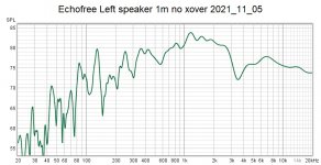 Echofree Left speaker 1m no xover 2021_11_05.jpg114.8 KB · Views: 79
 -
 Echofree Left speaker 1m separated Woofer_Mid_Twe clip 2021_11_05.jpg139.7 KB · Views: 68
 -
 Echofree Left speaker 1m Woofer 2021_11_05.jpg114 KB · Views: 66
 -
 Echofree Left speaker 1m Mid 2021_11_05.jpg115.2 KB · Views: 75
 -
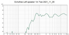 Echofree Left speaker 1m Twe 2021_11_05.jpg105.1 KB · Views: 98
Last edited:
Wow, Very interesting room, measurements not to shabby either.
A good take on a mini loudspeaker test centre, with nice soft furnishings.
Can you get impedance graphs and drop them into Xsim? with your new measurements, that should make it in terms of data to work from.
Your measurement's show how much more sensitivity you have in the tweeter and midrange.
The midrange does have more diffraction loss/Bafflestep than expected and the 1-3KHz behaviour and the tweeter peak at 800Hz will be interesting to see how they change when they are integrated by the crossover.
For the bass driver take the peaks and mentally join the dots to get the general trend of the arch of its response. If you can apply different smoothing 1octave smoothing should give you a feel for its shape.
I hope your new data makes you feel more positive about this.
Had take my mesaured curves for tweeter and midrange in my "echo-free" room, and put it in XSim and put all values from my xover in.
NO WOOFER AND NO IMPEDANCE CURVE IMPLEMETED! ( just to see how it look´s like in SPL)
And it look´s like this ?
Can´t understand where the differens come from, because this looks fine!
Regards John
NO WOOFER AND NO IMPEDANCE CURVE IMPLEMETED! ( just to see how it look´s like in SPL)
And it look´s like this ?
Can´t understand where the differens come from, because this looks fine
!Regards John
Attachments

- Home
- Loudspeakers
- Multi-Way
- 3 way upgrading Jamo D590 replacements and filter question