Emulator mark 2
Yeah, I'm a complete fool diffraction simulator response for all the apertures separately gives different results to what I demonstrated on the previous post rally with the simple emulator. This new emulation might be false as well so not sure if there is any value in all this. At least amount of voodoo is back up where it started
On this new version low pass alone doesn't provide too much narrowing for the pattern, some attenuation is required to get flat DI bandwidth. Extra delay is somewhat evil still but not for cardioid pattern, delay limits max DI.
Funny thing happens when attenuation on the back is about 6dB, the DI is flat all the way to sub frequencies. More or less attenuation narrows the flat DI bandwidth. Might be result of the current emulation setting and nothing to do with real world?
Tip, use the room tab in VituixCAD to approximate the position and toe in you might use the speaker to see in room response. While tuning the polar pattern, see what happens for the reflections Looks like cardioid is not best for close wall 45 degree toe-in position, some dipole (hyper cardioid) shows less wall interaction and is better in this regard. It is also higher DI overall. No idea what the sound would be with hyper cardioid mid, omni woofer and narrow horn on top.
Delay seems to be still an evil in this emulation, it limits the max DI achievable with low pass and attenuation. This is not a problem if DI about 6dB is fine. Hit DI above 7dB to get ~90 degree nominal dispersion on the front, but there is going to be some sound directly at the back. Nulls are at about 115 degrees and early reflections from front wall are low. Cardioid pattern itself, strongest null on the back, seems to be about 240 degrees nominal and much more early reflections. Maybe there is a way to have narrow main lobe and attenuation all the way around on the back? Cardioidish pattern where most of the attenuation is directly on the back seems to be DI about 6dB or below. This observation seems to hold true on both versions of the emulator so I believe it is true. Until the next revision of emulator comes in and makes me look fool again
Many things to tweak for your application and system! ps. The 4 apertures share the driver output, hense 6db attenuation block on front of the aperture drivers.
Yeah, I'm a complete fool
diffraction simulator response for all the apertures separately gives different results to what I demonstrated on the previous post rally with the simple emulator. This new emulation might be false as well so not sure if there is any value in all this. At least amount of voodoo is back up where it started On this new version low pass alone doesn't provide too much narrowing for the pattern, some attenuation is required to get flat DI bandwidth. Extra delay is somewhat evil still but not for cardioid pattern, delay limits max DI.
Funny thing happens when attenuation on the back is about 6dB, the DI is flat all the way to sub frequencies. More or less attenuation narrows the flat DI bandwidth. Might be result of the current emulation setting and nothing to do with real world?
Tip, use the room tab in VituixCAD to approximate the position and toe in you might use the speaker to see in room response. While tuning the polar pattern, see what happens for the reflections
Looks like cardioid is not best for close wall 45 degree toe-in position, some dipole (hyper cardioid) shows less wall interaction and is better in this regard. It is also higher DI overall. No idea what the sound would be with hyper cardioid mid, omni woofer and narrow horn on top. Delay seems to be still an evil in this emulation, it limits the max DI achievable with low pass and attenuation. This is not a problem if DI about 6dB is fine. Hit DI above 7dB to get ~90 degree nominal dispersion on the front, but there is going to be some sound directly at the back. Nulls are at about 115 degrees and early reflections from front wall are low. Cardioid pattern itself, strongest null on the back, seems to be about 240 degrees nominal and much more early reflections. Maybe there is a way to have narrow main lobe and attenuation all the way around on the back? Cardioidish pattern where most of the attenuation is directly on the back seems to be DI about 6dB or below. This observation seems to hold true on both versions of the emulator so I believe it is true. Until the next revision of emulator comes in and makes me look fool again
Many things to tweak for your application and system! ps. The 4 apertures share the driver output, hense 6db attenuation block on front of the aperture drivers.
Attachments
Last edited:
I have made some quick ABEC sims
"quick ABEC sims" is an oxymoron
No youtube videos from me but this guy has already made some that are very good
Austin Mys - YouTube
Austin Mys - YouTube
Fluid has posted so many ABEC sims so no wonder it is getting fast
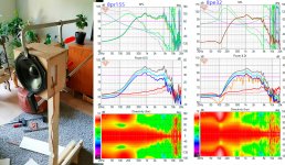
Another observation regarding rising DI of the prototypes. It is probably due to the damping material having better absorption on the high frequencies which steadily drops to about 200Hz and then falls like a rock. There might be some trick to have the lows take longer route on the box and have more attenuation to flatten the DI. Optimum attenuation would be around 6bB for widest bandwidth of flat DI.
Except, the proto box without any damping has also rising DI... so the reflections inside the box play major role I think. More over, with the new emulator version I can get similar bandwidth of narrow directivity as the bigger proto box with ~12dB or ~3dB attenuation, 12db attenuation has rising DI and the 3dB attenuation is flat DI. Couldn't figure out delay on the damping material yet, attenuation is probably something between 50-80% within the bandwidth questimating from datasheets, can it be that high, -6 - -12dB with 3cm of material? If attenuation was 12db would be great match to the emulator but falling absorption by frequency would then lower the attenuation on the lows and narrow the pattern (6db attenuation has narrowest pattern), which doesn't happen in the proto, or does it (the dipole quality on the low frequencies). Except the box without damping at all has similar main features on the directivity between all the reflections. Talk about voodoo, many variables at play.
Attachments
Last edited:
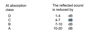
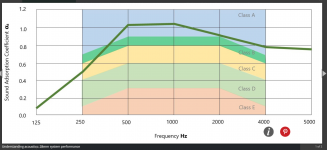
Found some hints from the web about some acoustic material about similar thickness for reference. Basically we'd want quite poor acoustic absorber, class B or C, for widest flat DI bandwidth. Thin material absorption factor drops in the 200 - 1000kHz region, especially below 500Hz. This would explain why the measurements polars get into the dipole territory below about 500Hz. Except the one proto without any damping is features similar polar pattern altough little bit higher in frequency so it is confusing.
Compressing the damping material would decrease its performance according abstract here:
Effects of compression on the sound absorption of fibrous materials | Request PDF
"During the compression of a fibrous mat, it is well known that the absorption properties are decreasing. "
There is a point squeecing the absorbing material in the aperture between some holed panels, tune the absorption closer to the 6dB "optimum". This would need separate measurement jig, or just tune with the prototype. 3D printing printing the aperture damping holders could bring repeatability to home DIY, or using some nuts and bolts with spacers to tune the compression. All this is pretty hard work, altough interesting for engineering minded. No wonder there is not many commercial products doing this passively.
Attachments
Last edited:
Tried to look for material that would have more constant absorption coefficient from ~200Hz and up but haven't found one yet. Found some papers about compressed porous materials but the results are mixed. Basically the absorption is too high most of the time. Tried to look for Feltmetal data and other metal meshes but couldn't find any yet. Asked few companies if they could hint about material that would have low and constant absorption coefficient. Most products seem to try to hit as high coefficient as possible. Acoustic fabrics in general seem to have lower coefficients but couldn't find promising one yet. Maybe some household fabric or multiple layers of would work just fine. Would be nice if suitable commercial product was found. 8c seems to use the Akoterm or similar Fluid posted in the beginning of this thread. Maybe they use it more intelligently, thin layer to get the high freq absorption down and then maybe some additional trickery to introduce more absorption to lows inside the cabinet. Steer highs out right away, somehow and let lows bounce a while inside the enclosure for more attenuation before they exit. Maybe quarterwave resonator inside?
dave123, Paalj, how your experiments are doing, any progress? Others?
dave123, Paalj, how your experiments are doing, any progress? Others?
Last edited:
Hi tmuikku,
I have not given up, but I am having a break
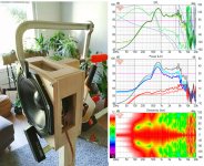
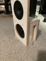
I am using the build and measure technique. The simulation seems to have a lot of variables
The ports is about 80mm behind baffle. I think it is quite close to the 8C. I will try different stuffing to try to hit better. The 8C seems to have about 10dB attenuation@90 deg. 200Hz. Not sure if this is measured in an anechoic chamber?
I have not given up, but I am having a break
I am using the build and measure technique. The simulation seems to have a lot of variables
The ports is about 80mm behind baffle. I think it is quite close to the 8C. I will try different stuffing to try to hit better. The 8C seems to have about 10dB attenuation@90 deg. 200Hz. Not sure if this is measured in an anechoic chamber?
Attachments
Hi tmuikku,
I have not given up, but I am having a break
I am using the build and measure technique. The simulation seems to have a lot of variables
The ports is about 80mm behind baffle. I think it is quite close to the 8C. I will try different stuffing to try to hit better. The 8C seems to have about 10dB attenuation@90 deg. 200Hz. Not sure if this is measured in an anechoic chamber?
I believe the exact type of stuffing used by Dutch & Dutch was posted by the designer of the speaker on here. Check his post history.
IIRC, it was specifically chosen for both:
1) it's ability to attenuate sound
2) and being non-toxic
IE, you may get better results from rockwool or fiberglass insulation, but those materials aren't as safe. The dude from Dutch & Dutch started out with rockwool, in the thread on diyaudio that predated their speakers.
Emulator guide
markbakk not yet, will check out, thanks!
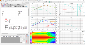
Meanwhile prepared little legend for the emulator so dave123 and paalj and anyone else can try it and perhaps comment their ideas and notions. If there is something crucial that is not right in the emulator or in the thinking maybe step forward, I already spent few days on this making all kinds of statements Emulator is just a VituixCAD project that utilizes some basic filters, gain and delay blocks and simulated baffle responses to emulate a real prototype box.
The purpose of the emulator is to try find out how the complicated interplay in this type of enclosure works and how to get the response anyone is looking for. I have tried to match the emulator to the real world prototype with measurements as best as I could with current knowledge to help understand what is going on. The measurements are done at home and the emulator is very much simplification of the real deal, but I think the main aspects can be inspected with simplified system emulation like this.
Once the emulator is kind of in the ball park to the real world specimen it is possible to tune the different variables and see how the response changes. Now it is easy to tune the damping material or see if there is too much or little delay somewhere, maybe the enclosure/aperture low pass should be more or less or what ever.
There are probably lots of things that don't make sense before spending some hours on thinking about this.
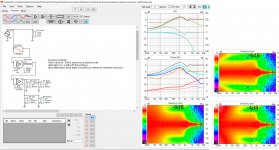
Here is how I'm using it:
I'm trying trying to get narrow pattern on the mid range speaker, with flat DI. The prototypes I built have narrow pattern but the DI is rising 200-1200kHz and I'd like to flatten that out as much as possible but don't know how yet. I would also like to extend the directivity a bit lower if possible. 8c demonstrates flat DI and extension should be possible.
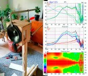
While tuning the various parameters on VituixCAD I'm looking at the polar map (Directivity window, horizontal and normalized) and the Power and DI window (red curve is DI, orange is in room response), the rest are not important at this point since the purpose is to find out what needs to be modified on the prototype to reach the target (directivity) I'm looking for. I tweak the parameters and see what happens to the graphs and try to reason what affects what. Besides the flat DI I'd like to get minimal room interaction, which means the deepest null of the pattern needs to be steered to match my listening room setup. For example I already observed that if there is too much delay inside the enclosure it is not possible to steer the deepest null to where I want and few other things. After finding out what needs to be changed to reach response I'm looking for it is time to figure out how to actually achieve that on the physical prototype. Maybe the damping material needs to be something specific, maybe the baffle needs to be wider or the apertures further back, can I build it with the tools I have and many other questions emerge.
Hope it helps everybody follow along and participate, I find this very interesting exercise and already got nice system with the prototype box but it would be cool to know how to build this kind of boxes, make some sense to the complexity.
Disclaimer: The emulator might be wrong like the previous one was few pages ago Lots of moving parts going on and some prior knowledge on things is required like what is DI and why one would want to have a flat DI or why it would be nice to widen the response around 200Hz or what ever. System specific stuff, everyone got their own projects to match.
It is important to realize the measured response deviates from the simplified ideal emulation attempt, where and why. Many questions still unanswered. Everyone welcome, time to learn VituixCAD have fun!
ps. emulator attached, it should contain responses simulated from my prototype dimensions. Feel free to make your own responses in the diffraction tool to match your own prototype, remember to change the XYZRT parameters on the drivers to match and load the new responses. Unzip to VituixCAD/projects/some-subfolder and open the project file in VituixCAD.
markbakk not yet, will check out, thanks!
Meanwhile prepared little legend for the emulator so dave123 and paalj and anyone else can try it and perhaps comment their ideas and notions. If there is something crucial that is not right in the emulator or in the thinking maybe step forward, I already spent few days on this making all kinds of statements
Emulator is just a VituixCAD project that utilizes some basic filters, gain and delay blocks and simulated baffle responses to emulate a real prototype box.The purpose of the emulator is to try find out how the complicated interplay in this type of enclosure works and how to get the response anyone is looking for. I have tried to match the emulator to the real world prototype with measurements as best as I could with current knowledge to help understand what is going on. The measurements are done at home and the emulator is very much simplification of the real deal, but I think the main aspects can be inspected with simplified system emulation like this.
Once the emulator is kind of in the ball park to the real world specimen it is possible to tune the different variables and see how the response changes. Now it is easy to tune the damping material or see if there is too much or little delay somewhere, maybe the enclosure/aperture low pass should be more or less or what ever.
There are probably lots of things that don't make sense before spending some hours on thinking about this.
Here is how I'm using it:
I'm trying trying to get narrow pattern on the mid range speaker, with flat DI. The prototypes I built have narrow pattern but the DI is rising 200-1200kHz and I'd like to flatten that out as much as possible but don't know how yet. I would also like to extend the directivity a bit lower if possible. 8c demonstrates flat DI and extension should be possible.
While tuning the various parameters on VituixCAD I'm looking at the polar map (Directivity window, horizontal and normalized) and the Power and DI window (red curve is DI, orange is in room response), the rest are not important at this point since the purpose is to find out what needs to be modified on the prototype to reach the target (directivity) I'm looking for. I tweak the parameters and see what happens to the graphs and try to reason what affects what. Besides the flat DI I'd like to get minimal room interaction, which means the deepest null of the pattern needs to be steered to match my listening room setup. For example I already observed that if there is too much delay inside the enclosure it is not possible to steer the deepest null to where I want and few other things. After finding out what needs to be changed to reach response I'm looking for it is time to figure out how to actually achieve that on the physical prototype. Maybe the damping material needs to be something specific, maybe the baffle needs to be wider or the apertures further back, can I build it with the tools I have and many other questions emerge.
Hope it helps everybody follow along and participate, I find this very interesting exercise and already got nice system with the prototype box but it would be cool to know how to build this kind of boxes, make some sense to the complexity.
Disclaimer: The emulator might be wrong like the previous one was few pages ago
Lots of moving parts going on and some prior knowledge on things is required like what is DI and why one would want to have a flat DI or why it would be nice to widen the response around 200Hz or what ever. System specific stuff, everyone got their own projects to match. It is important to realize the measured response deviates from the simplified ideal emulation attempt, where and why. Many questions still unanswered. Everyone welcome, time to learn VituixCAD
have fun!ps. emulator attached, it should contain responses simulated from my prototype dimensions. Feel free to make your own responses in the diffraction tool to match your own prototype, remember to change the XYZRT parameters on the drivers to match and load the new responses. Unzip to VituixCAD/projects/some-subfolder and open the project file in VituixCAD.
Attachments
Last edited:
Following text contains assumptions based on few tries on the emulator, so take it with grain of salt.
--
Found absorption coefficients for some melamine foam product:
http://www.soundservice.co.uk/documents/melamine.pdf
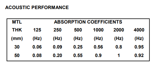
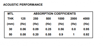
It looks like this is not suitable material. While the attenuation is more constant between ~200-1200Hz than some other materials it is only about 2dB at 250Hz in 50mm thickness. From the current emulation it looks like flat DI down to ~200Hz can be achieved with 4-9db attenuation. If this turns out to be true it would take so thick layer that the box would have to be very wide. For some projects that might be fine but I'd like to keep mine as small as possible to avoid diffraction and roundovers.
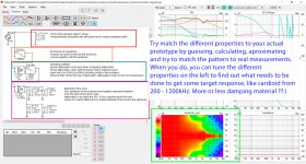
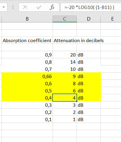
Here is quick table for suitable coefficients and attached emulation demonstrates effect of attenuation in the prototype, hopefully
This is the next thing I'd like to try in the prototype, more suitable damping material. If the logic is true the DI flatness target could be achieved with fess attenuation between 200 -500Hz
The current material in the prototype seems to have about 12db of attenuation to limit the flat DI bandwidth to 500Hz according to the emulation. I'm looking at the proto measurement and it shows these dipole pattern holes around 100Hz and I can't help but think the attenuation falls there through the optimal region but that could be something else entirely. Sure, it would correlate that many coefficient/frequency curves look like that, attenuation drops below 500Hz pretty fast, they all drop at some frequency sooner or later. I don't have absorption coefficients for the current damping material.
Anyway, looking for material that would have absorption coefficient around 0.2-0.7 and as steady as possible within the 200-1200Hz bandwidth. Compressing the material could reach the bracket, perhaps. If such material doesn't exists it is time to figure out something else Need to check out what they are using in 8c. Maybe the coefficients can be programmed to some function block in VituixCAD to see what happens to the response?
--
Found absorption coefficients for some melamine foam product:
http://www.soundservice.co.uk/documents/melamine.pdf
It looks like this is not suitable material. While the attenuation is more constant between ~200-1200Hz than some other materials it is only about 2dB at 250Hz in 50mm thickness. From the current emulation it looks like flat DI down to ~200Hz can be achieved with 4-9db attenuation. If this turns out to be true it would take so thick layer that the box would have to be very wide. For some projects that might be fine but I'd like to keep mine as small as possible to avoid diffraction and roundovers.
Here is quick table for suitable coefficients and attached emulation demonstrates effect of attenuation in the prototype, hopefully
This is the next thing I'd like to try in the prototype, more suitable damping material. If the logic is true the DI flatness target could be achieved with fess attenuation between 200 -500Hz
The current material in the prototype seems to have about 12db of attenuation to limit the flat DI bandwidth to 500Hz according to the emulation. I'm looking at the proto measurement and it shows these dipole pattern holes around 100Hz and I can't help but think the attenuation falls there through the optimal region but that could be something else entirely. Sure, it would correlate that many coefficient/frequency curves look like that, attenuation drops below 500Hz pretty fast, they all drop at some frequency sooner or later. I don't have absorption coefficients for the current damping material.
Anyway, looking for material that would have absorption coefficient around 0.2-0.7 and as steady as possible within the 200-1200Hz bandwidth. Compressing the material could reach the bracket, perhaps. If such material doesn't exists it is time to figure out something else
Need to check out what they are using in 8c. Maybe the coefficients can be programmed to some function block in VituixCAD to see what happens to the response?Attachments

Last edited:
Or even the links in this thread from earlierI believe the exact type of stuffing used by Dutch & Dutch was posted by the designer of the speaker on here. Check his post history.
Resistive port cardioid active speaker insipired by D&D 8C
Actually, the attenuation doesn't have to be constant. It is enough to be around 4-9dB there at the critical bandwidth I'm now falling short, between the 200-500Hz. The material I'm using has too much attenuation there, less thickness would be better. In this light there should be many materials that can do it. One can use the healthy products as well why not Thanks for the link fluid!
Anyone have idea how to make some biguad filter or transfer function from the absorption coefficients? I've got no glue. Simple low pass filter doesnt' match since the attenuation has limit and there is not steep enough shelving filter in vituixCAD to emulate the absorption of material so I'm out of tools trying this out.
Thanks for the link fluid!Anyone have idea how to make some biguad filter or transfer function from the absorption coefficients?
I've got no glue. Simple low pass filter doesnt' match since the attenuation has limit and there is not steep enough shelving filter in vituixCAD to emulate the absorption of material so I'm out of tools trying this out.
Last edited:
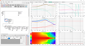
If I was going to try and simulate this in Vituix I would model the side ports as rectangular drivers with flat responses and use the baffle diffraction tool to simulate the side baffle and use these as the input and set the rotation and z parameters to put them in the right place. Then apply low pass, delay and attenuation to get what you want.Disclaimer: The emulator might be wrong like the previous one was few pages ago
The same can be done in ABEC by simulating a rectangular driver on the side with a lumped element script to mimic the damping etc.
This could be used to make a simulation match a measurement and with enough of them an accurate model could be made to apply to other situations. Or in reverse the best mix of parameters made and then experiment with materials to try and match them.
That is exactly how it is done in the current mark 2 version posted above, each side port has its own response done in diffraction tool. Thanks bringing this up, brings little more confidence it actually could work now
As long as the filters/attenuation/delays are approximately how they are in the prototype (response matching to measurements) it is possible to test if more or less something is needed. For example absolute low pass filter fc is not important, it is possible to test if it is good what it is or should it be more or less simply by varying that in vituixcad and see what happens, noo need to build another prototype blind
I think the damping material attenuation is what fools builders most. It is not simply more or less, optimum is - 6dB and above and below that responses look similar you'd need to know if you are above or below to be able to tune it to right direction. At least in this particular case. Meanwhile most materials go huge ramp up in attenuation just middle of the bandwidth, being always too low or too high and good only for small bandwidth, possibly outside where it should be. With right material and tgickness the ramp up in attenuation coefficients can be positioned there at lower end of our target bandwidth and have attenuation between 4-9dB to make use of it extending the flat DI lower instead of widening it early. High attenuation is not too bad with higher end of the bandwidth, actually it is good to kill reflections. If this is not right, all the other settings don't matter, anything i adjust helps the response only worsen it unless the attenuation is right. When the attenuation is right, the rest is just optimization like steering the null etc.
All learned by fiddling with the emulator, blame the emulation if it is false
As long as the filters/attenuation/delays are approximately how they are in the prototype (response matching to measurements) it is possible to test if more or less something is needed. For example absolute low pass filter fc is not important, it is possible to test if it is good what it is or should it be more or less simply by varying that in vituixcad and see what happens, noo need to build another prototype blind
I think the damping material attenuation is what fools builders most. It is not simply more or less, optimum is - 6dB and above and below that responses look similar
you'd need to know if you are above or below to be able to tune it to right direction. At least in this particular case. Meanwhile most materials go huge ramp up in attenuation just middle of the bandwidth, being always too low or too high and good only for small bandwidth, possibly outside where it should be. With right material and tgickness the ramp up in attenuation coefficients can be positioned there at lower end of our target bandwidth and have attenuation between 4-9dB to make use of it extending the flat DI lower instead of widening it early. High attenuation is not too bad with higher end of the bandwidth, actually it is good to kill reflections. If this is not right, all the other settings don't matter, anything i adjust helps the response only worsen it unless the attenuation is right. When the attenuation is right, the rest is just optimization like steering the null etc. All learned by fiddling with the emulator, blame the emulation if it is false
Last edited:
Not quite sure what you mean but cascading filters of the same type and frequency should get you whatever slope you want.Anyone have idea how to make some biguad filter or transfer function from the absorption coefficients?
I didn't see it described above but I checked the project file and that looks right to me. I'm not sure about the top and bottom vents but that's a different issueThat is exactly how it is done in the current mark 2 version posted above, each side port has its own response done in diffraction tool. Thanks bringing this up, brings little more confidence it actually could work now
- Home
- Loudspeakers
- Multi-Way
- Resistive port cardioid active speaker insipired by D&D 8C