cool stuff, thank you!
As far as I know basotect, or just melamine cleaning sponge, works fine for mid cardioid use. There are few projects on the forum, and that's what I've been using past few years. I still have basically the same prototypes as I've posted here on this thread. They work fine so went exploring other stuff meantime.
Melamine sponges are cheap and readily available, uniform and easy to use, but bit fiddly in a way, not knowing exact acoustic parameters of it. There are some impedance tube data for basotect online. In practice melamine foam works fine though, especially for DIY projects. I think it is quite brittle product, so it isn't likely best option for commercial products or high SPL application. This kind of proper acoustic product would be great to have. Will look into it.
Last edited:
The first picture is a great achievement and It seems to be the key to getting a uniform cardioid plot. I have a question. where is the best place for an acoustic flow resistor in Akabak ? Interior subdomain or Exterior? I tried both but the results were different.for the 5208:View attachment 1264914View attachment 1264915View attachment 1264916View attachment 1264917
for the PTT8:
View attachment 1264918View attachment 1264919View attachment 1264920View attachment 1264921
I think the PTT8 is pretty good as it stands. I hope to be able to improve the PTT8 with more work.
Last edited:
I wish I knew the answer to your question, I'm working in abec as I haven't made a serious effort to port my script to akabak. I also wish I knew what size/shape/material flow resistor would result in that picture.
I have the flow resistor in the interior subdomain. I think it might be best to make it its own sub-domain, with interfaces on both sides; one to the interior and one to the exterior.
You need absorption on interior surfaces modelling loose fill and then you need a flow resistor between interior and exterior. How best to model that flow resistor is TBD for me. A slot with absorbent surfaces is the best I can do today in ABEC.
Last edited:
Thank you. It helped me a lot and I think this is the correct way.I have the flow resistor in the interior subdomain. I think it might be best to make it its own sub-domain, with interfaces on both sides; one to the interior and one to the exterior.
The commercial version is indeed very expensive, but for those who aren’t already aware, there is a slowly evolving thread over at Audio Science Review, with the goal of developing a diy version At a reasonable cost. It requires some computer code to process all the measurements (seems to be mostly worked out at this point), and a practical way to make a whole lot of measurements at predefined mic locations. At least a large portion of the positioning would have to automated for the approach to be practical. Several interesting approaches have been proposed but a fully functioning system has not yet been hatched. Join the discussion if it’s of interest!The Klippel is indeed promising but what it promises to be to DIYers is too expensive.
Sorry for the brief diversion…
Few
They work well because the way how sound waves behave is extremely predictable at these lower frequencies.I think the Klippel NFS way is more promising. Vectoring the measured sound and thus make use of a 'field separation technique' works really wel in relatively small spaces. And even a NFS from the shelf is way cheaper than a serious anechoic room.
Also, most listening rooms are far to small to notice any directivity effects at these lower frequencies.
That's why there are room modes.
So in the end you barely gain anything.
I even find the practical use of a Klippel NFS very limited for a loudspeaker designer. There are a few special cases, but for the vast majority you won't find much other information that you can get in different ways. Either by measurements or simulations/calculations.
It's a bit different for reviewing loudspeakers.
100k is A LOT of money for even most companies.
For the same amount you can hire an additional R&D person or two.
Or even multiple people in production.
Renting an anechoic chamber once in a while is a lot cheaper.
If you already need that to begin with.
Obviously we don't have to build one ourselves, there are plenty of those available for rent.
True, one can get along without an NFS; we've been doing that for a long time. Nevertheless, i wish you had one so I could use it once in a while 🙂
Rent a medium sized sports venue instead and perform gated ground plane measurements with your own gear. It doesn’t come cheaper than that. 🤐They work well because the way how sound waves behave is extremely predictable at these lower frequencies.
Also, most listening rooms are far to small to notice any directivity effects at these lower frequencies.
That's why there are room modes.
So in the end you barely gain anything.
I even find the practical use of a Klippel NFS very limited for a loudspeaker designer. There are a few special cases, but for the vast majority you won't find much other information that you can get in different ways. Either by measurements or simulations/calculations.
It's a bit different for reviewing loudspeakers.
100k is A LOT of money for even most companies.
For the same amount you can hire an additional R&D person or two.
Or even multiple people in production.
Renting an anechoic chamber once in a while is a lot cheaper.
If you already need that to begin with.
Obviously we don't have to build one ourselves, there are plenty of those available for rent.
Yes it can get cheaper.Rent a medium sized sports venue instead and perform gated ground plane measurements with your own gear. It doesn’t come cheaper than that. 🤐
Just measure outside and plan accordingly.

Also, remember that as you go lower in freq. that you don’t need to have an anechoic result, what you do need is a clean enough result (semi-anechoic) - really that’s what a nearfield measurement is doing by providing a clean enough result that’s well above in Spl the pressure of the sound interacting with the room. Absorption can still be useful and at much lower freq.s Cepstral editing can also “clean-up” the result.
Where I live the snowy weather precludes outside measurements during the seasons I am most likely to work on speakers, and hauling speakers plus amplifiers plus a measuring system to a large venue isn't an option, so having an affordable and convenient measurement system at home that largely eliminates the room would be most welcome. Plus I just find the Klippel approach elegant and intriguing, so pursuing it is just another fun aspect of this hobby. Obviously everybody can and should use whatever approach suits their fancy and resources.
Few
Few
I remember seeing a factory tour when searching google photos.
https://www.google.com/search?sca_e...EAHVkbBWYQtKgLegQIEBAB&biw=1210&bih=790&dpr=2
https://www.google.com/search?sca_e...EAHVkbBWYQtKgLegQIEBAB&biw=1210&bih=790&dpr=2
Hello,
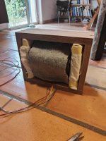
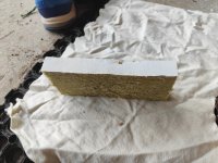
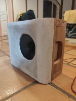
I have started some test with a phl 6" and two ports on the side walls. I tried with high density rockwool from sound panels and I think it is too dense, I can't feal anything whel I listen to the the ports...
I have ordered some magic sponges which should be made out of Melamine....
Back is closed with a baffle, inside it is 20 by 25 by 8 CMS.
Attachments
for a quick test, make a measurement from behind with and without your port +absorber in place
port sealed for no absorber measurement
I think you will do better the closer you place the port to the front. i.e. start right behind the baffle; pattern will hold higher with ports closer to front, and
you won't need as much absorption.
port sealed for no absorber measurement
I think you will do better the closer you place the port to the front. i.e. start right behind the baffle; pattern will hold higher with ports closer to front, and
you won't need as much absorption.
- Home
- Loudspeakers
- Multi-Way
- Resistive port cardioid active speaker insipired by D&D 8C


