Hey Dave123,
Any news on this? I am walking the same path and use the SEAS U22REX/P-SL. I have started with a cab depth of 120mm. I have done some indoor measurements, but there are a lot of reflections. Need to find time to move outdoors.
br,
Any news on this? I am walking the same path and use the SEAS U22REX/P-SL. I have started with a cab depth of 120mm. I have done some indoor measurements, but there are a lot of reflections. Need to find time to move outdoors.
br,
Attachments

Hi all, tried simple test with VituixCAD with 8" simulated ideal driver on minimal baffle and then tried to emulate a cardioid system by having two instances of the same output and then varying parameters of "the back side".
Not sure how well this corresponds to real world but in this particular test the only thing that is needed for cardioid response is low pass filter on the back. Not sure if the acoustic low pass is second order with resistance ports or what? It looks like increasing distance to front, increasing delay and increasing attenuation or lowering high pass frequency all widen the pattern. The higher the low pass frequency, lower the attenuation, less delay and distance to the front, the narrower the pattern until at some point it turns to dipole.
Few GIF files attached to demonstrate the various parameters:
attenuation, delay, low pass and distance.
edit. the files are too big, look here:
Dropbox - Kardioidi - Simplify your life
The polar map view is normalized for better view of the pattern. Look for the red line of the left middle (Power and DI) window to see the DI slope.
Last edited:
Ah, was it a glitch in the software? Can't seem to get it working again after shutting down the program. 😀 will investigate
The software worked, had to rotate the back driver 🙂
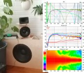
Alright, got prototype system whipped up and made some measurements over the weekend. Looks like a box with holes works already, a low pass filter like the emulation suggested. But the real world is not as simple as the simulator and the driver structure seems to play its part etc. so what ever cardioid one pursues it helps to build a prototype system where the various configurations can be tested within reasonable time to find most suitable configuration of box volume, damping material and holes with the given driver.
Since only the low pass seems to be what is required for narrow pattern I decided to only care about the low pass and leave other variables to be sacrificed for ease of build. Formula for acoustic low pass is found for example here Acoustic Filter | Article about Acoustic Filter by The Free Dictionary . Corner frequency fc = ( c / pi ) * sqrt(S/IV). There are probably million variables at play with a box like this but the simple ones to adjust are S = combined area of the ports and V = volume of the box. From the emulations I posted earlier one can reason what happens when the low pass frequency is varied. Use the box dimensions for all the variables in the formula to get into ball park. Now build a box, measure it and see if S or V needs to adjusted for performance you are looking for. I kept the damping material simple and used one layer of 3cm thick insulation around the box, avoiding the voodoo. As emulations suggested attenuation and delay by the damping material seems to widen the pattern so I thought less is better. The attenuation of the back wave seems to be mainly trade-off between bass extension and narrow pattern. Simplified, more attenuation means more bass and wide patter, less attenuation means no bass and narrower pattern.
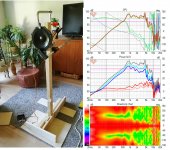
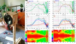
Few photos attached. Measurements are semi anechoic livingroom setup with 15 deg steps 0 - 180, rest is filled in and visualized with VituixCAD. The polar maps are normalized to on axis. The driver is 8" FaitalPro 8pr155. Tried 8pe32 as well which gave a bit different response despite the box being the same. This led me to believe best box/driver combination is found only by measuring prototypes.
I've got freestanding STH100 above and old 15" bass box below, simulated system response looks pretty nice. I have no means to measure spinorama of the complete system, but the simulation shows practically no diffraction and smooth directivity within the measurement resolution and accuracy of the individual components. I find it easy to make mistakes with the measurements, simulation parameters and DSP (sigma studio) so no final verdict, sounds nice though 🙂
ps. there is tons of information on the thread and other threads so I'm not writing it all here intentionally. Cardioid mid was not hard thing to pull off, but needs some DIY dedication, it is not paint by numbers. I encourage everyone to try since the cardioid box itself can solve many "problems" with cost of low frequency extension, which can be added back by simply having another woofer for it. I'm not counting extra prototypes as trade-off since that is the fun time 😀
Alright, got prototype system whipped up and made some measurements over the weekend. Looks like a box with holes works already, a low pass filter like the emulation suggested. But the real world is not as simple as the simulator and the driver structure seems to play its part etc. so what ever cardioid one pursues it helps to build a prototype system where the various configurations can be tested within reasonable time to find most suitable configuration of box volume, damping material and holes with the given driver.
Since only the low pass seems to be what is required for narrow pattern I decided to only care about the low pass and leave other variables to be sacrificed for ease of build. Formula for acoustic low pass is found for example here Acoustic Filter | Article about Acoustic Filter by The Free Dictionary . Corner frequency fc = ( c / pi ) * sqrt(S/IV). There are probably million variables at play with a box like this but the simple ones to adjust are S = combined area of the ports and V = volume of the box. From the emulations I posted earlier one can reason what happens when the low pass frequency is varied. Use the box dimensions for all the variables in the formula to get into ball park. Now build a box, measure it and see if S or V needs to adjusted for performance you are looking for. I kept the damping material simple and used one layer of 3cm thick insulation around the box, avoiding the voodoo. As emulations suggested attenuation and delay by the damping material seems to widen the pattern so I thought less is better. The attenuation of the back wave seems to be mainly trade-off between bass extension and narrow pattern. Simplified, more attenuation means more bass and wide patter, less attenuation means no bass and narrower pattern.
Few photos attached. Measurements are semi anechoic livingroom setup with 15 deg steps 0 - 180, rest is filled in and visualized with VituixCAD. The polar maps are normalized to on axis. The driver is 8" FaitalPro 8pr155. Tried 8pe32 as well which gave a bit different response despite the box being the same. This led me to believe best box/driver combination is found only by measuring prototypes.
I've got freestanding STH100 above and old 15" bass box below, simulated system response looks pretty nice. I have no means to measure spinorama of the complete system, but the simulation shows practically no diffraction and smooth directivity within the measurement resolution and accuracy of the individual components. I find it easy to make mistakes with the measurements, simulation parameters and DSP (sigma studio) so no final verdict, sounds nice though 🙂
ps. there is tons of information on the thread and other threads so I'm not writing it all here intentionally. Cardioid mid was not hard thing to pull off, but needs some DIY dedication, it is not paint by numbers. I encourage everyone to try since the cardioid box itself can solve many "problems" with cost of low frequency extension, which can be added back by simply having another woofer for it. I'm not counting extra prototypes as trade-off since that is the fun time 😀
Attachments

Last edited:
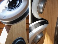
I think you can improve it even further by making a bunch of "slits" with some wood.
This will increase the flow resistance quite significantly due to the boundary effect.
Next is to fill these slits with some damping material.
This will increase the flow resistance quite significantly due to the boundary effect.
Next is to fill these slits with some damping material.
Hi b_force, do you have information how the flow resistance affects? I referred this as voodoo since it is always mentioned even in the name of such enclosure but actual information seems so light it feels like black magic, no way to simulate directly in loudspeaker concept. Keeps people from trying things out 🙂 What the resistance does? increases attenuation and delay? According to the emulation few posts back both seem increase low end response and widen the pattern which doesn't feel improvement to me currently. I'm very new to this, it was my first try on it and led to working application so I'm happy for the moment. Anyway, the simplified model thinking the back side just as a acoustic low pass seemed to work nicely at least this time, even though my thinking / conclusions might be wrong.
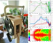
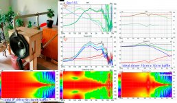
Edit time over, so a new post: compare the first and second attachments, the naked driver and just a box behind acting as acoustic low pass. From the polar map you see the "dipole quality" drops from about 3kHz to about 900Hz or so, without any resistance at all. This is further lowered with a bit deeper box and some damping, didn't measure the deeper box without damping material, I should have. Added damping material seems to reduce all kinds of ripple off axis (third image), probably attenuating the reflections inside the box just enough. Fourth image halves the aperture area lowering the low pass frequency and the cardioidish pattern extends a bit lower still like the emulations kind of suggest. Next image doubles the volume and keeps the simplified acoustic low pass model frequency about the same compared to small box with halved aperture area and the response is almost the same, altought bit smoother. There is difference but for the bandwidth it is going to operate the response stays almost the same. I think the driver structure is part of the low pass.
Alright, all evidence points to data I want to see so by definition my conclusions are wrong 😀 I would like to believe it is all about the low pass though, add in some damping and call it a day would be nice. Voodoo flushed to the drain, bye bye 🙂 From this one experiment it looks like the low pass is at least one factor to tune in.
Making the pattern more constant would be nice, maybe the slits and resistance helps. A project for another weekend sometime in the future.
Last edited:
Hi b_force, do you have information how the flow resistance affects? I referred this as voodoo since it is always mentioned even in the name of such enclosure but actual information seems so light it feels like black magic, no way to simulate directly in loudspeaker concept. Keeps people from trying things out 🙂 What the resistance does? increases attenuation and delay? According to the emulation few posts back both seem increase low end response and widen the pattern which doesn't feel improvement to me currently. I'm very new to this, it was my first try on it and led to working application so I'm happy for the moment. Anyway, the simplified model thinking the back side just as a acoustic low pass seemed to work nicely at least this time, even though my thinking / conclusions might be wrong.
I'm not b_force, but I think I can answer this one.
If you look at how a TQWT works, the more you reduce the size of the vent, the lower the box plays. But at the same time, the low frequency efficiency suffers.
So I would expect that masking off part of the vent, using steel mesh or the like, should have a similar effect.
Gradient did that in the Helsinki speaker.
Attachments
Thanks Patric Bateman, this seems to be the case, acoustic cancellation forms the pattern by making the power disappear. The narrower the pattern on given frequency the less power. Emulations few posts back show this as well, not sure if the emulation has any resemblance of real world but that is the thing I was able to imagine without thinking about the resistance. There is no acoustic resistance element in the simulator 🙂 Used two ideal drivers with diffraction simulated responses on the vituixCAD, flip the other around. Add low pass, attenuation and delay elements to the back driver and play with back side Z value. See GIF:s in the dropbox link to visualize how the different parameters make directivity increase and what happens to power response while directivity increases. The low pass seems to be the only element needed to increase directivity and is present on all the GIFs. Delay or attenuation or distance increase in the back signal seems to widen the pattern. Without the low pass the pattern is dipole. Emulations suggest the meat is the low pass 🙂 Is there something else?
Quote from Olli Kantamaa masters thesis 2020
"5.6.4 Acoustical Resistance Enclosure
Acoustical resistance can be used in a loudspeaker enclosure to control directivity (Holmes
1986, Iding 1971). Frequency dependent resistance controls the radiation pattern. Leaking
negative signal attenuates the rear radiation. Material with frequency dependent resistance covers leaking structure in the enclosure. Enclosure acts as sealed enclosure for
higher frequencies where the acoustic resistance is high. Resistance enclosure produces
cardioid radiation pattern in LF range (Gunness 2018, Balogh 1977).
Frequency dependent acoustic resistance defines the leaked frequency band and the
directivity pattern. Material used to resist the airflow defines the acoustic resistance
(Iding 1971). The acoustic resistance enclosure causes the system cut–off frequency to
rise. Acoustic resistance enclosure has poor LF sensitivity compared to sealed of reflex
enclosures (Iding 1971). Controlling the directional pattern is difficult due the non–linear
acoustic resistance found in typically used materials (Backman 1999)."
All this reads to me that the resistance means acoustic low pass and attenuation 😀 the info is probably on the referenced papers
Last edited:
The resistance box and active cardioid are basically doing the same thing, one by electronic the other by acoustical means.The low pass seems to be the only element needed to increase directivity and is present on all the GIFs. Delay or attenuation or distance increase in the back signal seems to widen the pattern. Without the low pass the pattern is dipole. Emulations suggest the meat is the low pass 🙂 Is there something else?
An IIR low pass has delay, the group delay of the filter, by tuning the group delay through filter type and frequency you can change the pattern.
The most flexible way to play around is to use a linear phase low pass and then add the delay electronically this allows you control over the two variables separately rather than being linked together.
Where the active side woofers or resistive openings are located affects the delay needed to get the right pattern at the intended frequency. In the resistance box all of the different options change the effect of the acoustic low pass filter and they are much harder to model the response of, hence the black magic experimentation to get it right.

Thanks for the info fluid! Active solution seems to give more control but the veil around the leaky box starts to move aside, a bit at least 🙂 low pass and position it is, slits or single big hole shouldn't make too much difference then. If the low pass frequency and slope stays the same all that matters is how far back the acoustical center of the back side is.
Was able to aproximate the difference between the small and large box in the emulation by changing Z distance of the back driver instance few centimeters. The low pass frequency is affected besides the box volume, size of apertures and speed of sound. The damping material should affect the speed of sound at least a little, lowering the low pass frequency? If the c in the formula was bit under 300m/s I'd get bang on results match in the emulation vs. reality just by the properties of the box inserted into the acoustic low pass function and adjusting emulation Z to approximate center of the apertures. If this is true and not mere coincidence here is the recipe: build smallish box, add in some damping material to smoothen the response, fine tune the pattern with the aperture size (low pass) and distance from the front (delay of the low pass) and this can be done with couple left over wood pieces and clamps if the holes were made a bit oversized in the prototype. Not too complicated after all? 😀 In fact there seems to be a lot of leeway, the low pass frequency is not too critical neither is the distance as long as it all is in the ball park the system should be workable. Commercial products probably want to tweak the performance as much as possible though.
Was able to aproximate the difference between the small and large box in the emulation by changing Z distance of the back driver instance few centimeters. The low pass frequency is affected besides the box volume, size of apertures and speed of sound. The damping material should affect the speed of sound at least a little, lowering the low pass frequency? If the c in the formula was bit under 300m/s I'd get bang on results match in the emulation vs. reality just by the properties of the box inserted into the acoustic low pass function and adjusting emulation Z to approximate center of the apertures. If this is true and not mere coincidence here is the recipe: build smallish box, add in some damping material to smoothen the response, fine tune the pattern with the aperture size (low pass) and distance from the front (delay of the low pass) and this can be done with couple left over wood pieces and clamps if the holes were made a bit oversized in the prototype. Not too complicated after all? 😀 In fact there seems to be a lot of leeway, the low pass frequency is not too critical neither is the distance as long as it all is in the ball park the system should be workable. Commercial products probably want to tweak the performance as much as possible though.
Last edited:
edit time over, here is the ps. can't get the pattern control much lower in frequency than what is there in the data posted, to about 300-500Hz. 8C probably relies to the back woofers to extend pattern control lower. Maybe a bit better can be achieved but can't see how all the way from ~1.2k to ~100Hz would play out with single driver in a leaky box.
In your measurements you have only got a cardioidish response from 200 to 400Hz. The 15" has more directivity at the crossover and you could have most likely got a very similar pattern from the 3 drivers without the openings by tuning the mid enclosure size.Not too complicated after all? 😀
The sort of pattern D&D get is smoother and more consistent but they have less directivity at the upper end so it is easier to blend. Getting just the right balance of flow resistance, delay and opening size is not easy, there is no magic but finding the right set of parameters takes experimentation or access to a ton of accurate material data to feed into comsol. I don't mean to be negative but your results show you are affecting a pretty small bandwidth.
If you put the active drivers on the side it is much easier to extend the bandwidth of pattern control because to extend it higher needs less delay.edit time over, here is the ps. can't get the pattern control much lower in frequency than what is there in the data posted, to about 300-500Hz. 8C probably relies to the back woofers to extend pattern control lower. Maybe a bit better can be achieved but can't see how all the way from ~1.2k to ~100Hz would play out with single driver in a leaky box.
Have a look at this thread here and in the pages before where kimmo has given some good instructions on simulating active cardioids in vituix.
VituixCAD v2 - Page 5
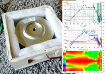
There seems to be a lot of low frequency dipole in your results suggesting not enough flow resistance or too big ports, the box looks to be too leaky 😉
Hi b_force, do you have information how the flow resistance affects? I referred this as voodoo since it is always mentioned even in the name of such enclosure but actual information seems so light it feels like black magic, no way to simulate directly in loudspeaker concept. Keeps people from trying things out 🙂 What the resistance does? increases attenuation and delay? According to the emulation few posts back both seem increase low end response and widen the pattern which doesn't feel improvement to me currently. I'm very new to this, it was my first try on it and led to working application so I'm happy for the moment. Anyway, the simplified model thinking the back side just as a acoustic low pass seemed to work nicely at least this time, even though my thinking / conclusions might be wrong.
Voodoo?
Ever heard of the boundary layer effect?
Plenty of information out there, so I have no idea what you're talking about.
Anyway, it's a common technique used in general acoustics.
Last edited:
Would a "box" like this be doable with a 15" midbassdriver like a td15m? If so, what frequency span would you think it could do? 80-200hz?
This looks like another project for my CNC. I have a pair of BC 8PE21 laying around. Maybe not the best speaker for this purpose, but should be good enough for the test. I also have some fullrange 6" car speakers, which might work as well. I foresee a larger opening and then adding inserts for tuning. It is very easy to drill a zillion of 4 mm holes on a CNC🙂
In your measurements you have only got a cardioidish response from 200 to 400Hz. The 15" has more directivity at the crossover and you could have most likely got a very similar pattern from the 3 drivers without the openings by tuning the mid enclosure size.
The sort of pattern D&D get is smoother and more consistent but they have less directivity at the upper end so it is easier to blend. Getting just the right balance of flow resistance, delay and opening size is not easy, there is no magic but finding the right set of parameters takes experimentation or access to a ton of accurate material data to feed into comsol. I don't mean to be negative but your results show you are affecting a pretty small bandwidth.
You see I'm trying to get around the lots of complicated data 😀 Could you please indicate which measurement you talk about so I can learn from this? the 15" is what I had laying around and it doesn't sound too good above 200Hz or so. Sims look a bit better with higher xo, this was lowest good sim with acceptable sound from the 15" box, around 300Hz I think.
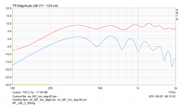
To me it looks like the pattern is narrower than with the same sized closed box from about ~1khz (beaming starts) down to ~400Hz where response is still 10db down at 90 degrees to side, almost two octaves, and back is some 20db down. I've got no idea what ideal cardioid response would be, I just don't want sound to the sides and back. The directivity rises with frequency on my test, it is not constant like 8C, but is very smooth all the way.
Normal 8" driver would have DI near 0 at 400Hz already with minimal baffle. It looks like baffle of about 70cm x 70cm is needed to get some green color on the polar map on the side of 8" driver at 400Hz and mitigating the diffraction would need substantial roundovers. so, kind of confused what you refer to? I'm still not getting what the resistance is and how it affects?😀
Attachments
Last edited:
- Home
- Loudspeakers
- Multi-Way
- Resistive port cardioid active speaker insipired by D&D 8C