Adding to the earlier post: There is kind of relation to low pass filtering on the damping material because of the absorption rises with frequency. But, this is not to mistaken to low pass filter since it is form of a shelving filter, doesn't attenuate to infinity, only by some 20dB or so depending on the material and thickness. I can't make cardioid response with shelving filter on vituixCAD, low pass is required. edit. can be done with only delay as well.
^ fluid, yes this is exactly what I'm doing with the simulator. There is no way to simulate what happens inside the enclosure other than trying to approximate the phenomena with the simple filters / attenuation / delays. Purpose of this ideal model, simplification, is to try to figure out what affects what. Merely try to figure out using the filters what would happen if there is more damping or less, or higher or lower fc for the low pass. The question is when there is no need for attenuation on the back signal, or any extra delay, why would there be need for resistance? The cardioid pattern seems to emerge just from the acoustic low pass of the enclosure, which in itself doesn't require any damping. If you want high flat DI do not put any attenuation in, use acoustic low pass which can be done without any damping material. Altough, it could be so that suitable low pass is not doable and the delay needs to be adjusted with damping material as well.
Ok we need delay for the cardioid response, can be pure delay or some low pass filter. But attenuation only worsens the response, makes it wider. I see delay can be added with acoustic resistance? But that adds attenuation as well? If it is pure delay, then it would be all that is needed.
Anyway, if this is the verdict then there is no need to have black magic on the system. Just use as little damping material as possible and get the port location right to equalize the delays between front and back to the port.
Last edited:
sorry, edit time over again on the previous post and the text is not very accurate to what I tried to output. Here is attempt to demonstrate. Fluid, others, please say straight up what I don't understand if this below is wrong, thanks 🙂
Ok here 4 attachments to demonstrate what the simple phenomena emulation tell me:
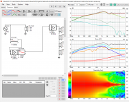
1. only delay inside the box to form "cardioidish" pattern. In the prototype it would need to be about 7cm.
2. Lets assume 7cm of delay is done with damping material the damping material would have to introduce some attenuation, lets add moderate 3dB of attenuation. Cool, could achieve the response I'm after, flattish 6dB DI down to ~200Hz.
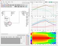
3. Same can be achieved with low pass filter, 1st order slope or any other I tried, bessel in the attachment, the fc more or less with the different slopes and the pattern looks a bit different. Main thing we have flattish DI down to about 200Hz very easily, no matter what the slope and the fc is not that critical. Higher fc = higher DI. Notice there is no attenuation, no damping material, no breaking sweat at all, easy task, just a low pass from the hip.
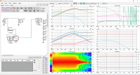
4. Lets add some attenuation for the mere low pass filter. It looks like we can add about 3dB attenuation to still achieve the flat DI down to ~200Hz. Any more and the flat DI bandwidth goes. Added delay lowers the DI.
To get 7cm of delay with damping material the attenuation would be huge?
To get acoustic low pass one needs only perforations to the enclosure is needed, no need for damping material, right?
If the logic is true(?) we have a set of rules to build enclosure like this.
To achieve cardioidish pattern with flat DI to as low frequency as possible only thing one needs to do is: add delay to the back signal of the cone without adding attenuation.
Ok now anyone tuning a cardioid box, here is the tip how to do it:
If prototype response is not correct, reduce the damping material until it is. If it doesn't work without damping material at all, change how the apertures are arranged to affect path length difference between front and back and the low pass. You need less delay on the back signal = higher low pass fc and/or shorter path length difference between in and outside.
Maybe some combination of damping material and low pass characteristic is needed to get the required delay and response in reality? Some damping material would be nice to kill reflections / smoothen the response. Delay and attenuation both harm the response and you'd need to widen the enclosure etc. to negate the delay and take the attenuation out one way or the other. This might be reason why the 8c is width as it is, to have enough damping material for the DI they are after.
Anyway, I feel these are the variables to play with.
I think I know how to verify this for false or true with measurements. Measure the prototype with changing the low pass (block the holes) as well as remove the attenuation. Also need to get clear picture what the response looks like if there is too much or too little delay on the back, how does it look like to get a feel what to adjust in that situation.
Confusion about need for exact attenuation, exact absorption coefficients I've written about recently came from the emulation where I had all sides connected in parallel I needed some attenuation to reach cardioid response. Still not 100% sure why I'd need attenuation on the parallel connection and no attenuation on the series connection in the VituixCAD.. Anyway, this would be nice to clear out as well 🙂 Any other problemos?
Ok here 4 attachments to demonstrate what the simple phenomena emulation tell me:
1. only delay inside the box to form "cardioidish" pattern. In the prototype it would need to be about 7cm.
2. Lets assume 7cm of delay is done with damping material the damping material would have to introduce some attenuation, lets add moderate 3dB of attenuation. Cool, could achieve the response I'm after, flattish 6dB DI down to ~200Hz.
3. Same can be achieved with low pass filter, 1st order slope or any other I tried, bessel in the attachment, the fc more or less with the different slopes and the pattern looks a bit different. Main thing we have flattish DI down to about 200Hz very easily, no matter what the slope and the fc is not that critical. Higher fc = higher DI. Notice there is no attenuation, no damping material, no breaking sweat at all, easy task, just a low pass from the hip.
4. Lets add some attenuation for the mere low pass filter. It looks like we can add about 3dB attenuation to still achieve the flat DI down to ~200Hz. Any more and the flat DI bandwidth goes. Added delay lowers the DI.
To get 7cm of delay with damping material the attenuation would be huge?
To get acoustic low pass one needs only perforations to the enclosure is needed, no need for damping material, right?
If the logic is true(?) we have a set of rules to build enclosure like this.
To achieve cardioidish pattern with flat DI to as low frequency as possible only thing one needs to do is: add delay to the back signal of the cone without adding attenuation.
Ok now anyone tuning a cardioid box, here is the tip how to do it:
If prototype response is not correct, reduce the damping material until it is. If it doesn't work without damping material at all, change how the apertures are arranged to affect path length difference between front and back and the low pass. You need less delay on the back signal = higher low pass fc and/or shorter path length difference between in and outside.
Maybe some combination of damping material and low pass characteristic is needed to get the required delay and response in reality? Some damping material would be nice to kill reflections / smoothen the response. Delay and attenuation both harm the response and you'd need to widen the enclosure etc. to negate the delay and take the attenuation out one way or the other. This might be reason why the 8c is width as it is, to have enough damping material for the DI they are after.
Anyway, I feel these are the variables to play with.
I think I know how to verify this for false or true with measurements. Measure the prototype with changing the low pass (block the holes) as well as remove the attenuation. Also need to get clear picture what the response looks like if there is too much or too little delay on the back, how does it look like to get a feel what to adjust in that situation.
Confusion about need for exact attenuation, exact absorption coefficients I've written about recently came from the emulation where I had all sides connected in parallel I needed some attenuation to reach cardioid response. Still not 100% sure why I'd need attenuation on the parallel connection and no attenuation on the series connection in the VituixCAD.. Anyway, this would be nice to clear out as well 🙂 Any other problemos?
Attachments
Last edited:
The absorption coefficients are actually complex numbers. Usually just the magnitude is specified in attenuation tables. Most of the tables are created using a "room loss" model and the materials are relaxed (not compressed). It's possible that a simpler attenuation model does not accurately reflect absorption pass through loss, phase (delay) and reflection due to the impedance change.
The complex coefficients could be obtained using acoustic impedance tube measurements and used in a BEM model. I don't know how VCAD models it but it might be where the difference is.
The complex coefficients could be obtained using acoustic impedance tube measurements and used in a BEM model. I don't know how VCAD models it but it might be where the difference is.
Yes I thought so that more accurate way of simulating the damping material attenuation would be needed to get closer match to the measurements. Do you have thoughts about generalizing on this so we wouldn't have to go to specifics? Like is there some coefficients / characterization of coefficients you would look for? it looks like most materials go the rapid rise of attenuation right on the bandwidth we are trying to control here. Is that the worst case? Would it be better to have material that goes most of the transition (to higher coefficients) below the bandwidth <200Hz or above >500Hz or so maybe? I've tried simple shelving filter to approximate the slope a bit on VCAD and to me it looks like the attenuation is just bad for the performance especially on the low end of the bandwidth.
What do you think about all this otherwise, is there any validity in the general reasoning so far?
Currently trying to figure out what kind of slopes would acoustic filters have but no luck. First order filter in the emulation seems to be closest to the measurements. Just trying to zone in more accurately. But now it is time to hang out with the kids, the wife looks angry too so better go now 😀
Last edited:
No design generalizations yet. Good stuff in this thread.
I'm interested in cardiods but have yet to try to build one. Still busy on other projects.
I have an acoustic impedance tube so I can measure material and create a "profile" . The results are actually complex coefficients but the graphs just show magnitude. Modular active 3 way - work in progress
Then I can use the measurements in a BEM model Modular active 3 way - work in progress
That should be enough to create a cardiod model, but have not actually tried it.
That would be cool if you can measure and produce the data! I have no idea how to include something like that to VituixCAD though. Any data and insight would be welcome in any case 🙂
Wow, advanced stuff on your thread, nice! https://www.diyaudio.com/forums/multi-way/326926-modular-active-3-progress-34.html#post6641589 has fiberglass measurements attached, seems fine for this application being rather constant for the >200Hz and up bandwidth. Just need to find out how thick layer to use. Delay would be cool to have but attenuation looks like it is bad for the pattern but good for smoothing out reflections.
Does the impedance tube measurements tell the delay, is it in the data already? is it similarly "constant" as attenuation and how much? What happens with compression, does the delay and attenuation vary separately? Very interesting, thanks chiming in with real stuff!
Last edited:
Alright, I think I mentioned earlier cardioidish response is not achieved by shelving filter only. That seems to be false with the emulator having all side ports connected in series or my mistakes in the earlier experiments 😀 See few attachments that demonstrate some variations of the shelving filter.
Shelving filter is to imitate the fact that damping material has rising absorption coefficient by frequency and shelving filter is closest simple filter to mimic this phenomenon.
Playing around with it for awhile got following observations:
- the attenuation (of material) can be anything at least up to -20dB (coefficient >0,8) as long as the slope rises gently and fc of the filter is relatively high (> 300Hz).
-Low attenuation with 1st order shelving filter shows highest DI so the ramp up on absorption coefficients on the acoustic material used should be as slow as possible and the ramp up needs to happen higher up in frequency the more the max attenuation of the material is. When there is 6dB (0,5) max absorption the ramp up can be lower in frequency than with 20dB max absorption (> 0,8).
-With 20db max absorption the 1st order filter at ~600Hz shows DI about 6dB. If the max absorption is 6dB then the filter can be half that at 300Hz to achieve similar 6dB flat DI.
Alright, so the melamine sponges could be actually good material here contrary what I commented last week. Well, different simulation, different results 😀
So indeed, plain acoustic damping material can introduce enough delay for cardioidish pattern to emerge because of the absorption coefficients making a shelving filter of sorts. Here again, additional delay and attenuation is lowering DI so less is better. Ramping up absorption coefficients high up in frequency seems to be better, melamine should be better in this application than the Ewona I'm using for example, or fiberclass above. Melamine had very low coefficients on low frequencies and then ramps up. Need to buy some material before weekend, there is possibility to do measurements on Saturday.
If I try to roughly approximate the Ewona wool I'm using in the prototypes, ramping up ~200Hz with steep slope (2nd order shelving is the max I can do now) more than 12dB attenuation above and the pattern falls apart to rising DI like in the measurements. This can be fixed to flat high DI by using much higher fc (ramping up >400Hz ), slower slope (1st order) and less max attenuation = thinner layer of different kind damping material.
Activating the additional acoustic low pass emulation of the apertures won't have much effect on the polar when the fc of both the shelving and low pass filters are sufficiently high = small box with large apertures with right kind of damping material (last attachment).
Sorry about the back and forth with the conclusions 😀 Please step forwards when you see something going wrong, I'm just interpreting what I'm seeing and you are doing the same. I'm no professional on acoustics and prefer to be corrected, the info is for all 🙂
Attachments
Last edited:
Fiddling with the parameters, trying to figure out if some fabric would be better than the insulation products. They seem to have very slow ramp up, for example this I found https://www.akustiikkapalvelut.fi/tiedostot/foscusan_alfa.pdf
If the ramp up is slow and max attenuation is reached very high up in frequency (many kHz). There has to be acoustic low pass in addition to get the delay required to get rid of the dipole pattern.
It looks like suitable acoustic material has absorption coefficient ramp up slow and end up to 20dB absorption around 1-2kHz perhaps, top end of the bandwidth we are dealing with. Most of the materials I checked eventually end up to 20dB attenuation at some frequency. The attenuation / slope / fc can be relaxed when there is the acoustic low pass of the enclosure to help. If the acoustic low pass is suitable, the damping material is not needed, maybe it has to be some combination of both in reality.
Mixed bag conclusions. Still, no damping material needed to get the pattern if the acoustic low pass of enclosure and apertures is good. I don't know if this is possible to achieve in reality so we can use absorption material that adds more delay with the shelving filter property it has. Less absorption is better so the shelving should happen slowly and right frequency to add the delay of the filter but not much attenuation to the low end of the bandwidth we are trying to control the pattern. If the fc is too high like with the example fabric, additional acoustic low pass is required to get rid of the dipole pattern. If the material has fast ramp up to high absorption on low frequencies already the flat DI cannot be achieved. I'd approximate that the right material for box with high acoustic low pass filter is something thin, but thicker than acoustic fabric, maybe felt or something. Or perhaps compressed thicker material?
Attached is a GIF that has four shelving filter fc variations, 200, 300, 500 and 1000Hz. Fc more than that and the response approaches dipole. The Ewona I'm using has very roughly 200Hz fc. The melamine foam few pages page is close to the 1000Hz filter, much better cardioidish response with that.
Rough rule of thumb for shopping suitable material for apertures for box like this (small box, big apertures = high low pass) could be: absorption coefficient close to 0 around the low end of the bandwidth we want to control the pattern (200Hz), and the max around the upper end of the bandwidth (1200Hz) and the pattern can be achieved.
Attachments
Last edited:
Gosh, edit time over and attachemt has turned in to jpg. Here is the GIF
Attachments

Last edited:
The rule of thumb is not very good, a ~4" driver in minimal enclosure seems to work fine with similar settings as the 8". 15" driver needs some more delay so different damping material with ramp up would be better bit lower like the Ewona perhaps. No need to worry about acoustic low pass if it is high enough = small enclosure with big holes.
All from the emulator, which can still be wrong 🙂 Would have to build and measure these to find out, or if you have knowledge please share, thanks!
All from the emulator, which can still be wrong 🙂 Would have to build and measure these to find out, or if you have knowledge please share, thanks!
Attachments
Last edited:
That is almost too good to be true but I don't want to throw any stones at it! I think you should be able to build a good wide dispersion system around it. Might have to array it to get enough output...
I wonder if a cardioid box would be a benefit for a 10" coaxial like in this post: Fixing the Stereo Phantom Center
Or maybe using this 8" coaxial should get a smaller box: Test Bench: Celestion FTX0820 8-inch Coaxial Woofer/Compression Driver | audioXpress
Or maybe using this 8" coaxial should get a smaller box: Test Bench: Celestion FTX0820 8-inch Coaxial Woofer/Compression Driver | audioXpress
^^ Hi nc535, yeah usually there is something wrong with free lunch 🙂 The polars look very good, no limiting factors for wide flat DI bandwidth other than the driver size (high frequencies beam and rise the DI) and too much resistance. Gotta remember all the low end is lost in the process so the overall usable bandwidth isn't that wide, maybe the 2-3 octaves below the driver diameter wavelengths, as often mentioned. I don't know how they would array, or would it work to stack them in multiple different sizes. Seems to work fine between waveguide and traditional boxed woofer though. One would need more driver(s) below the box to handle the lows so it is 3 way system at least.
Power drops about the same as DI rises around the two octave down 250Hz mark, so about 6dB down at the low end of the bandwidth for cardioidish response and a little more for hypercardioidish. Not too bad drop for pro audio drivers with plenty of power handling capability for home use, one would lose some output to bafflestep on small baffle anyway. These aspects in mind I don't think stacking is necessary if I'm interpreting it correctly. I'm reading all this from the emulation, reality might be different?
Well, measurements are needed to confirm all this emulation driven knowledge true or false so all this is kind of academic for now.
Pelanj, it looks like any size driver is fine as long as the enclosure is as small as possible for the driver. This is what I have been playing with, enclosure as small as possible. No idea how it works with something else. Difference between 8" and 10" seems to be miniscule, both will lose the lows and beam the highs roughly at the same frequencies give or take some hertz. There is probably some reasons to fine tune the enclosure/driver size in reality though.
Last edited:
Yeah go for it! If you prepare it so that you can test various things like different port sizes, if you want to play with the acoustic low pass filter, maybe plan how to adjust the depth somehow to see if you can smooth the response out, maybe have some different damping materials to try out. Happy prototyping!
Please post your findings if possible, thanks. I might have time this weekend to do more measurements so maybe there is some additional info available soon. Hopefully the emulator example and knowledge extracted from it is helpful while tuning the response!🙂
Please post your findings if possible, thanks. I might have time this weekend to do more measurements so maybe there is some additional info available soon. Hopefully the emulator example and knowledge extracted from it is helpful while tuning the response!🙂
Last edited:
Time to measure some more. I need to find a 100pack of these melamin sponges😀
If it dosen't work, I can wash my car a lot.
If it dosen't work, I can wash my car a lot.
Measurements with melamine sponges
Only bought 4 melamine sponges and the result looks what was expected, win!😎 Luckily it was raining today so couldn't do renovation. Measurement time! Melamine provided almost flat DI all the way below 100Hz, nice 🙂
Measured about 10 variations, made many observations:
1. not sure how reliable the low end data is, the shape of polar map at low frequencies depend a bit on the windowing time in IR to FR conversion. Be sure to measure prototype variations on the same day/setup and use same IR to FR conversion settings (windowing) on all variations so the results remain comparable between each other.
2. Melamine sponges seem to work nice and are readily available but are a bit brittle. The performance is subject to change if the melamine is fingered during the years.
3. Did measurements twice for few configurations where other configurations were tested in between. The results are similar on the ~1kHz region but the flat DI doesn't reach as low and group delay rises faster on the lows. Not sure why is this but it indicates that either the melamine sponges were already damaged, some leak somewhere or some other small thing. Anyway, building a pair of speaker requires prototyping and then building two exact copies of that 😀 Use damping material from same patch etc. what ever you can to get close response for the two boxes.
4. It is hard to get flat DI and even harder to get over 6dB, too easy to get too much attenuation / delay. I managed to get a bit different results with the deep and shallow boxes. The deeper box has a bit rising DI shy of 5dB around 200Hz and almost 6dB at 500Hz. The shallower looks to have this almost reversed, goes towards hypercardioidish on lower frequencies. I suspect there is depth for the box where the balance is a bit better than either I have. Depth of the box affects the delays and attenuation inside the box.
5. Not sure why the response is similar when there is ewona at the apertures or nothing at all! The other is not enough delay difference(?) and the other is lots of attenuation(?). Might be same thing, what? It is too late night for thinking it through 😀
I've got some felt ordered but it didn't make it for this weekend so more measurements on some future date. I've got a hunch felt type stuff could replace the melamine, at least I hope so. Looks like the material needs to be chosen for the application anyway.
I was able to get better response with the help from the emulation so looks it like that anyone can now tune their boxes with better rate of success with these few simple things to consider. Delay and attenuation. Both kill the response if too much. And it is easy to get too much. I couldn't get hypercardioid response this time, DI > 6dB. The measurement setup was same as last time, only thing changed is melamine sponges instead of Ewona wool on the apertures.
I think the box acoustic low pass should be pushed as high as possible to be able to reach a target response with the damping material "alone", or use no damping material at all to get the response with path length difference "alone" or acoustic low pass "alone". The latter are hard to pull off so the I think most suitable way to manufacture this kind of passive cardioid box at home is to get the acoustic low pass high as possible and just use the damping material properties to get a response. In general, if you don't have flat and "high" DI on your project try to rise up your acoustic low pass fc by enlarging the apertures (without adding path difference) / using smaller volume and change your damping material to more suitable one (rather thin / less or no absorption on low frequencies).
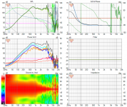
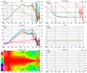
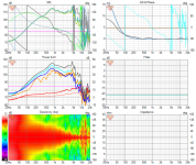
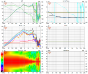
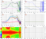
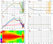
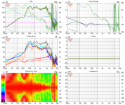
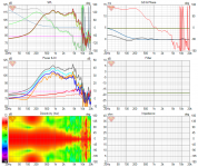
Some sixpacks attached for amusement. Polar maps are normalized. 13 measurements 0-180 on 15 deg steps and around 4ms windowing, VituixCAD fills in the rest. Try to read the image names for what measurement configuration they represent. Hope it helps 🙂
Only bought 4 melamine sponges and the result looks what was expected, win!😎 Luckily it was raining today so couldn't do renovation. Measurement time! Melamine provided almost flat DI all the way below 100Hz, nice 🙂
Measured about 10 variations, made many observations:
1. not sure how reliable the low end data is, the shape of polar map at low frequencies depend a bit on the windowing time in IR to FR conversion. Be sure to measure prototype variations on the same day/setup and use same IR to FR conversion settings (windowing) on all variations so the results remain comparable between each other.
2. Melamine sponges seem to work nice and are readily available but are a bit brittle. The performance is subject to change if the melamine is fingered during the years.
3. Did measurements twice for few configurations where other configurations were tested in between. The results are similar on the ~1kHz region but the flat DI doesn't reach as low and group delay rises faster on the lows. Not sure why is this but it indicates that either the melamine sponges were already damaged, some leak somewhere or some other small thing. Anyway, building a pair of speaker requires prototyping and then building two exact copies of that 😀 Use damping material from same patch etc. what ever you can to get close response for the two boxes.
4. It is hard to get flat DI and even harder to get over 6dB, too easy to get too much attenuation / delay. I managed to get a bit different results with the deep and shallow boxes. The deeper box has a bit rising DI shy of 5dB around 200Hz and almost 6dB at 500Hz. The shallower looks to have this almost reversed, goes towards hypercardioidish on lower frequencies. I suspect there is depth for the box where the balance is a bit better than either I have. Depth of the box affects the delays and attenuation inside the box.
5. Not sure why the response is similar when there is ewona at the apertures or nothing at all! The other is not enough delay difference(?) and the other is lots of attenuation(?). Might be same thing, what? It is too late night for thinking it through 😀
I've got some felt ordered but it didn't make it for this weekend so more measurements on some future date. I've got a hunch felt type stuff could replace the melamine, at least I hope so. Looks like the material needs to be chosen for the application anyway.
I was able to get better response with the help from the emulation so looks it like that anyone can now tune their boxes with better rate of success with these few simple things to consider. Delay and attenuation. Both kill the response if too much. And it is easy to get too much. I couldn't get hypercardioid response this time, DI > 6dB. The measurement setup was same as last time, only thing changed is melamine sponges instead of Ewona wool on the apertures.
I think the box acoustic low pass should be pushed as high as possible to be able to reach a target response with the damping material "alone", or use no damping material at all to get the response with path length difference "alone" or acoustic low pass "alone". The latter are hard to pull off so the I think most suitable way to manufacture this kind of passive cardioid box at home is to get the acoustic low pass high as possible and just use the damping material properties to get a response. In general, if you don't have flat and "high" DI on your project try to rise up your acoustic low pass fc by enlarging the apertures (without adding path difference) / using smaller volume and change your damping material to more suitable one (rather thin / less or no absorption on low frequencies).
Some sixpacks attached for amusement. Polar maps are normalized. 13 measurements 0-180 on 15 deg steps and around 4ms windowing, VituixCAD fills in the rest. Try to read the image names for what measurement configuration they represent. Hope it helps 🙂
Attachments
-
 small-box-melamine-big-apertures-no-back-fill.png202.5 KB · Views: 193
 -
 small-box-melamine-and-back-fill.png198.4 KB · Views: 195
 -
 small-box-melamine-no-back-fill.png200.5 KB · Views: 189
 -
 big-box-melamine-and 1-layer-back-fill-repeated.png202.9 KB · Views: 192
 -
 big-box-melamine-and-1-layer-back-fill.png193.4 KB · Views: 310
 -
 big-box-only-back-fill.png201.5 KB · Views: 306
 -
 big-box-melamine-no-back-fill.png194.6 KB · Views: 287
 -
 big-box - no fill.png209.1 KB · Views: 287
 -
 control-big-box-with-ewona-allround-from-previous-measurement-set.png199.5 KB · Views: 332

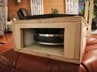
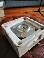
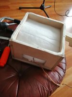
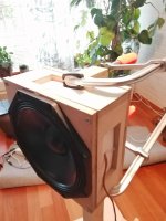
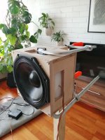
Few photos that relate to the measurements. Small and big box are the same as few weeks ago. Some picks showing the melamine sponges I got from the grocery store to replace the Ewona wool on the apertures. I measured the opposite side of the wire.
One more observation I forgot to mention. The attenuation roughly > 100 degrees on most of the configurations was enough to make the pattern very noticeable to ear altough the DI is quite low on the low mids. When the speaker was at certain rotation me listening off axis (roughly > 100 degrees) the sound seemed to emerge from the wall in front of the speaker and not from the speaker itself. Almost all configurations are workable, after switching to melamine (or any suitable damping material) it is only matter of fine tuning playing with the box size and possible back fill, attenuation material at the back of the box.
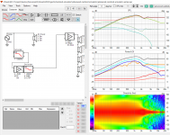
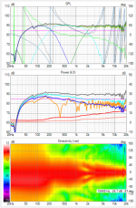
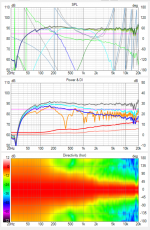
Also updated whole system simulation views attached showing both horizontal and vertical response. Note this is not measurement of the system but simulation from measurements of the 3 ways separately. Tried RTA in REW and the bad predicted in room response dip around ~400Hz and beyond seem to be pretty much spot on in reality. So watch out that orange trace on your VituixCAD projects everyone 🙂 Also, I always have some issues on the sound when DSP is programmed to the sims so better check with ear and RTA to finalize 🙂
One more observation I forgot to mention. The attenuation roughly > 100 degrees on most of the configurations was enough to make the pattern very noticeable to ear altough the DI is quite low on the low mids. When the speaker was at certain rotation me listening off axis (roughly > 100 degrees) the sound seemed to emerge from the wall in front of the speaker and not from the speaker itself. Almost all configurations are workable, after switching to melamine (or any suitable damping material) it is only matter of fine tuning playing with the box size and possible back fill, attenuation material at the back of the box.
Also updated whole system simulation views attached showing both horizontal and vertical response. Note this is not measurement of the system but simulation from measurements of the 3 ways separately. Tried RTA in REW and the bad predicted in room response dip around ~400Hz and beyond seem to be pretty much spot on in reality. So watch out that orange trace on your VituixCAD projects everyone 🙂 Also, I always have some issues on the sound when DSP is programmed to the sims so better check with ear and RTA to finalize 🙂
Attachments
-
 small-box-big-apertures.jpeg483.1 KB · Views: 262
 -
 small-box-melamine-no-back-fill.jpg303.5 KB · Views: 252
 -
 big-box-melamine-and-1-layer-back-fill.jpg422.4 KB · Views: 232
 -
 small-box.jpg299.7 KB · Views: 233
 -
 big-box.jpg461.6 KB · Views: 271
 -
 new-xo-11.9.2021-ver.png422.6 KB · Views: 266
 -
 new-xo-11.9.2021-hor.png406.9 KB · Views: 269
Last edited:
Edit time over: I used large box with melamine on the ports and one layer of Ewona wool on the back but just because it was last configuration I measured, could have used the small box as well before killed it with the enlarged apertures 😀
Not sure why enlargening the apertures killed the smooth response. The damping material was now in the apertures = further away from the driver frame with more space for driver to breathe past the melamine first. Less attenuation perhaps, maybe too high acoustic low pass, maybe change in path difference or any combination of various reasons. Anyway, shows that it is not all in the damping material. Hopefully everyone gets their projects tuned in, eventually 🙂
Not sure why enlargening the apertures killed the smooth response. The damping material was now in the apertures = further away from the driver frame with more space for driver to breathe past the melamine first. Less attenuation perhaps, maybe too high acoustic low pass, maybe change in path difference or any combination of various reasons. Anyway, shows that it is not all in the damping material. Hopefully everyone gets their projects tuned in, eventually 🙂
Last edited:
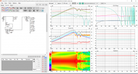
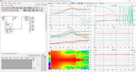
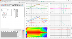
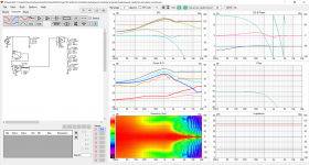
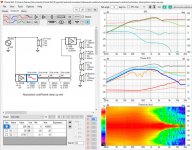
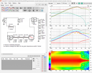
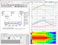
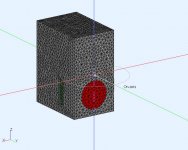
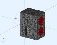
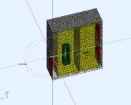
I put together a simplified BEM model of the DD8C to help get some insight on how it's working. Hopefully it can sync up with the VCAD work.
The driver electrical models (easy data) are 2*DSA205-4 8" subs, DSA215-8 8" woofer. The box (divided in 2 chambers ~15L each) and the ports are 30x160x60mm ID. The DD spec'd XO are [100Hz, 1250Hz] LR linear phase however I have used [130Hz,1250Hz] LR4 min phase because is was easier and my drivers are different. If it turns out that I need min phase filter I can generate them in RePhase and import them.
The 8C is suppose to be mounted on a stand near a wall (~Pi space). My model is in 4Pi space so it requires 12dB LF EQ over Pi space. It also required EQ for the sealed subs to stretch the roll over to @30Hz. Both EQ's were applied, as well as a woofer time delay to sync up with the sub forward wavefront.
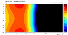
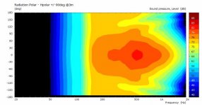
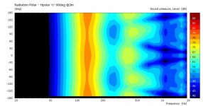
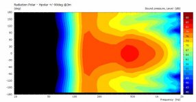
This first pass does not have any resistive material in the port. It's acting like a high tuned BR using the initial geometry. It's still showing some control over the horizontal beamwidth as there is a sudden narrowing from subs to woofer at XO. It looks like the subs are not required for this mid-bass cardioid pattern so they will be discarded in next model. The polars are for the horizontal +/-180deg.
pics 1,2,3 : the BEM model, uses 1/2 symmetry
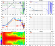
pics 4 : subwoofer contribution
pics 5 : woofer front contribution
pics 6 : port contributions
pics 7 : woofer + port
pics 8 : sub + woofer + port
.
The driver electrical models (easy data) are 2*DSA205-4 8" subs, DSA215-8 8" woofer. The box (divided in 2 chambers ~15L each) and the ports are 30x160x60mm ID. The DD spec'd XO are [100Hz, 1250Hz] LR linear phase however I have used [130Hz,1250Hz] LR4 min phase because is was easier and my drivers are different. If it turns out that I need min phase filter I can generate them in RePhase and import them.
The 8C is suppose to be mounted on a stand near a wall (~Pi space). My model is in 4Pi space so it requires 12dB LF EQ over Pi space. It also required EQ for the sealed subs to stretch the roll over to @30Hz. Both EQ's were applied, as well as a woofer time delay to sync up with the sub forward wavefront.
This first pass does not have any resistive material in the port. It's acting like a high tuned BR using the initial geometry. It's still showing some control over the horizontal beamwidth as there is a sudden narrowing from subs to woofer at XO. It looks like the subs are not required for this mid-bass cardioid pattern so they will be discarded in next model. The polars are for the horizontal +/-180deg.
pics 1,2,3 : the BEM model, uses 1/2 symmetry
pics 4 : subwoofer contribution
pics 5 : woofer front contribution
pics 6 : port contributions
pics 7 : woofer + port
pics 8 : sub + woofer + port
.
Attachments
-
 DD8C-1.jpg68.1 KB · Views: 190
 -
 DD8C-2.jpg70.7 KB · Views: 190
 -
 DD8C-3.jpg72.4 KB · Views: 202
 -
 Subwoofer contribution.jpg26.1 KB · Views: 210
 -
 Woofer contribution.jpg30 KB · Views: 171
 -
 Port contribution.jpg34.2 KB · Views: 170
 -
 Woofer+Port.jpg30.5 KB · Views: 180
 -
 Sub+Woofer+Port.jpg29.8 KB · Views: 183
Last edited:
- Home
- Loudspeakers
- Multi-Way
- Resistive port cardioid active speaker insipired by D&D 8C