Not quite sure what you mean but cascading filters of the same type and frequency should get you whatever slope you want.
A damping material does not provide constant attenuation but the attenuation varies with frequency and I'd like to model that more accurately in the vituixCAD. Attenuation could be <1dB at 100Hz, 4dB at 200Hz and 12dB at 500Hz and maybe 20dB at >1000Hz and I'd like to emulate this. The data is in form of absorption coefficients published along with most acoustic materials. I can approximate it with shelving filter but the important slope is not correct, the slope is the important part, it is right there around the important band I'm trying to improve on the prototype.
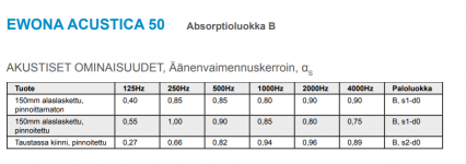
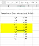
I'm using Finnish Ewona insulation material. Their acoustic products have coefficients in the datasheet. See the other attached table to translate coefficients to dB of attenuation. https://ewona.fi/wp-content/uploads/2020/03/tuotekortti_acustica50_1.5.pdf
According the logic I'd need the coefficients to be between 0.4-0.9 on the 200-500Hz bandwidth to get flat DI and extend the flat DI bandwidth towards 100Hz. The Ewona has that absorption range too low in frequency, below 200Hz. I think this makes the measurements of my prototype box have the Dipole response below 200Hz as you commented few days ago. I'd like to move that to be above 200Hz and test that with the emulator somehow. I already know 6db attenuation is best, but the ramp of attenuation across bandwidth is hard to emulate with the simple filters.
I didn't see it described above but I checked the project file and that looks right to me. I'm not sure about the top and bottom vents but that's a different issue
I forgot to describe the side ports, sorry, too much information and my english typing fingers are so much slower than my Finnish Savonian thought process it gets frustrating fast 😀 My writings are long and windy, sorry all, try to follow along if you are interested.
Top and bottom can be verified by changing the polar plot between vertical and horizontal, they are the same like they should on a symmetrical device. I had to diffraction sim them all sides separately (left, right, top, bottom) because the R and T rotations are not enough to translate the surface to right position and you could immediately see that in the polar plot(s). If the port was on the middle of the side panel then two diff sims would be enough for the available rotations.
Attachments
Last edited:
Looking at the Ewona coefficients (previous post attachment) they are pretty constant between >250Hz! Great, I need to find thin sheet somewhere. Top two rows on the table are "with 150mm airgap behind", the other is with surface coating. The bottom row is "attached to surface". I think the airgap row represents the situation in this application (the aperture). 0.85 coefficient means 16dB of attenuation and I'd need half that. If 1cm+ Ewona thickness is not available I need to change brand. Still waiting coefficients for the Ewona insulation board I have, different product altough it might be close to what the acoustic products in the table above are.
Last edited:
Again, the problem is that the absorption coefficient (attenuation) goes up right there in the low mids on all acoustic damping materials I've checked. Stacking layers of thin product can be used to tune to right attenuation if the attenuation (absorption coefficient) lower than required, 1-4dB. Many products have too much attenuation like the Ewona I'm using, I'd need much thinner layer of it.
Other option is to utilize the rising absorption bandwidth, there the attenuation is right momentarily even if the material is too thick / too much attenuation. Meaning that most materials the attenuation is either too low or too high in the 200-500Hz band and that is where my prototype differs most from the 8c. The window for good attenuation is rather narrow, between 4-9 decibels. Find right material that ramps up the absorption from 4-9dB on the 200-500Hz bandwidth and all should be golden... If the emulation and logic is true 😀 Might be something else entirely, never know before testing this theory with new damping material and measurements. Or figure out a way to model the absorption coefficients in the vituixCAD to get closer approximation of the prototype in the emulator.
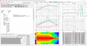
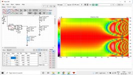
Current version of the emulator can demonstrate constant attenuation of 6dB yields flat DI all the way to sub frequencies and verifies constant attenuation of 4 to 9dB the bracket that enables constant DI down to 200Hz. More than 9dB or less than 4dB attenuation and the DI is rising like in my prototype. This was demonstrated in post #235 with VituixCAD screenshot.
Other option is to utilize the rising absorption bandwidth, there the attenuation is right momentarily even if the material is too thick / too much attenuation. Meaning that most materials the attenuation is either too low or too high in the 200-500Hz band and that is where my prototype differs most from the 8c. The window for good attenuation is rather narrow, between 4-9 decibels. Find right material that ramps up the absorption from 4-9dB on the 200-500Hz bandwidth and all should be golden... If the emulation and logic is true 😀 Might be something else entirely, never know before testing this theory with new damping material and measurements. Or figure out a way to model the absorption coefficients in the vituixCAD to get closer approximation of the prototype in the emulator.
Current version of the emulator can demonstrate constant attenuation of 6dB yields flat DI all the way to sub frequencies and verifies constant attenuation of 4 to 9dB the bracket that enables constant DI down to 200Hz. More than 9dB or less than 4dB attenuation and the DI is rising like in my prototype. This was demonstrated in post #235 with VituixCAD screenshot.
Last edited:
Following with greatest interest. I think that an ATH generated freestanding waveguide would work fine with cardioid mid and a 15" for bass - that sounds like a nice and compact system to me (compared to my cellar monster horn system). I only have a vague idea on how to do this and also I do not know what to expect from the simulation. I am ready to experiment when I will understand more.
I suggest you to build fast prototype or two with different variations that feel important to you at the moment. It is mostly about physical dimensions so scale up what you have seen so far with the smaller drivers for starting point. Measure it and try to figure out what is happening, why the polar pattern is what it is. Use the VituixCAD diffraction tool to recreate the prototype (dimensions and features) with ideal response and load them in into the emulation project. Now you can tinker with the various simplified parameters of the prototype box in the software. This will lead your thought process and help to tweak the response without too much unknowns and need to build million prototypes. With the emulation you can find answers to questions you find with the prototype. Have fun!😀
In addition to controlling directivity this kind of box solves many small problems of multiway mid range speaker trading off low frequency extension and extra cost of all this prototyping and thinking. Trying to reduce the cost part with the emulator and low frequency extension can be fixed adding traditional monster boxed/horn woofer 😉 For these reasons I value passive cardioid mid range very good compromise overall for achieving better sound quality system, at the moment. No idea what happens after the journey ends, I might value some other things 😀 Anyway
The box can be very small, easy and cheap to build, measure and handle and is visually unobtrusive. It is acoustically small in the bandwidth it is used for minimized footprint to the sound. Not much diffraction or standing waves or other silly problems due to a box. Ability to tweak directivity to match the waveguide and woofer below at will would be cool. Altought there are limits what can be achieved directivity wise (there could be reason 8c has very wide polars, higher flat DI seems to be more difficult to achieve ). Passive cardioid is not as flexible system as active and is not for fullrange or two way aficionados because the low frequency power is lost in the process.
Last edited:
Following with greatest interest. I think that an ATH generated freestanding waveguide would work fine with cardioid mid and a 15" for bass - that sounds like a nice and compact system to me (compared to my cellar monster horn system). I only have a vague idea on how to do this and also I do not know what to expect from the simulation. I am ready to experiment when I will understand more.
Quote from Kimmo
Few random thoughts about cardioid for bass and low mid.
Single cardioid radiator with DI~5 dB is not very impressive amount of directivity. It's usually audible and subjectively significant (though not clearly visible in statistical features). Big boxed cone e.g. 15" is as directive down to 300 Hz so main goal for complex narrow/small designs such as narrow resistance box or low-passed side woofers in narrow cabinet is to be small and more beautiful than big box.
But if speakers can be in any ~ in the best places (close enough or far enough from front wall and corners) and also listening point can be optimized, there is not much need for cardioid bass.
Cardioid Loudspeakers - Are they worth it? | Page 3 | Audio Science Review (ASR) Forum
Small drivers with small boxes can be more beautiful (and easier to handle) but also acoustically small. I mean the cardioid box is smallest thing one can build, unless using a naked driver dipole. Waveguide works from the opposite side, takes the small tweeter to big physical dimensions. Now one is able to crossover the two without either disturbing the other physically too much. Dipole takes this even further but can't be positioned right at the wall I think. Not sure how well the directivities would match if big waveguide with small cardioid woofer box, I don't have bigger waveguide at the moment to test with. Just a thought 🙂
Help, lend me your brain! The emulation shows that when there is four apertures the optimal additional attenuation (with damping material) to get flat DI would be 6dB. This is equal to attenuation of sound power to each aperture since the four apertures each receive 1/4 of the rear sound = equal to front side of the driver of course.
Now if I block two of the apertures (mute top and bottom in emulation) and reduce the portion to each open ones accordingly to receive 1/2 of the rear sound power to reflect reality. Now the optimal attenuation of damping material for flat DI seems to be 3dB which is again as much as each aperture receives sound. Power to each "hole" is emulated by the gain block near the side drivers on the VituixCAD. Gain block next to the text is the "perfect damping material" emulating attenuation. When both of these gain blocks have the same attenuation, a flat DI is achieved.
What is the relation here, how to interpret this for the real prototype? Is it that attenuation of each aperture should be 3dB = attenuate half the power / output which is 3dB of attenuation no matter how many there is? my brain is twisted!😀 Am I confusing power or volts or something with this kind of emulation setup in VituixCAD, multiple drivers simulating the four holes? What is going on? Thanks!
Attached GIF to demonstrate on the emulator. Don't mind the graphs jumping around, they are pretty much about the same, scale changes for some reason. Polars change a bit due to top and bottom holes being closed. In reality the acoustic low pass filter would change by halving the aperture area but this doesn't seem to affect too much when the attenuation is right (flat DI down to subs) so I didn't change low pass on the test.
edit. there is relation in this observation to the simple emulation I posted back in post #183 that emulated the rear side with just one driver and showd 0dB additional attenuation was optimum, no sharing power to various amount of apertures, no additional attenuation needed. Is this the emulation, or is this something that happens for real when trying to achieve narrow pattern with single loudspeaker driver?
Attachments
Last edited:
Technically, there is no need of attenuation. The simulation needs attenuation only to simulate the division of rear energy into 2 or 4 slots of a real world case, thats all.
If you simulate the rear slots as 4 drivers in series parallel combination then there is no need to attenuate. Do note, you can only simulate 4 drivers but not 2 this way.
If you simulate the rear slots as 4 drivers in series parallel combination then there is no need to attenuate. Do note, you can only simulate 4 drivers but not 2 this way.
Last edited:
I was studying side photos of Dutch and Dutch 8C and noticed that the side port is over 4 inches depth, I was wondering why not less than 4 inches (for 8 inch driver). It looks like the material inside provides additional delay and so to compensate for that it has been advanced acoustically by increasing the depth of the slot to little over 4 inches. Does anyone agree?
^^Thanks, could you post demonstration to help me understand? I'm not sure how the voltages and series parallel stuff works out here since the outputs are not actual drivers with impedance et. all, just ideal sources simulated responses? Anyway, this confusion should be removed to get more sense on this subject.
edit. tried it, series attenuates of course, same effect if I just use the separate gain block and all drivers parallel after it. Situation remains the same, any additional attenuation to this backside signal hampers the response.
^ My logic says position of the hole depends on the delays inside the box. The output through a hole needs to have same delay as sound from the front, around the edge, when they meet at the hole (delay difference affects where the null is steered). For this reason, due to the driver cone being "recessed" the path outside is longer than inside from any given point on the driver diaphragm to any point on either side. To increase path length to the port outside the box relative to inside the port needs to be set back and baffle widened for greatest "catch up". As you increase baffle width and pull the port back on the side both in and outside path length increases, if you do only one of them (pull port back or widen the baffle) the path length difference doesn't change much. Hence the port is pulled back from the baffle about as much as the baffle extends the woofer, simplified equilateral triangle, maximum path difference. Point is to increase the path length outside more than path length inside. The more the damping adds additional delay to increase path length inside the enclosure, the more back the port needs to be to compensate for the delay (and wider baffle, given the enclosure is rectangular). The outside path length needs to be brought to equal with the inside.
I'm ever more confused about all this though, the emulations show any damping and delay inside the box seem to harm the response (reduce flat DI bandwidth and DI itself). Why dampen at all? What is the reason for name "resistance enclosure" when any resistance (attenuation or delay) is bad for the response? What piece of puzzle is missing from the emulations?
Last edited:
I was studying side photos of Dutch and Dutch 8C and noticed that the side port is over 4 inches depth, I was wondering why not less than 4 inches (for 8 inch driver). It looks like the material inside provides additional delay and so to compensate for that it has been advanced acoustically by increasing the depth of the slot to little over 4 inches. Does anyone agree?
If you go to their facebook page, you can find some mechincal drawings, which basically show how they do it.
Or just read on Martijn's old DIY thread from many years ago.
Or just write him a message, he probably will be more than happy to help you out.
Move your ports back or use an FIR filter for low pass then you will see the effect of the delay more. At the moment you have hardly any z depth so the group delay from the low pass only needs to be small to get the right pattern.I'm ever more confused about all this though, the emulations show any damping and delay inside the box seem to harm the response (reduce flat DI bandwidth and DI itself). Why dampen at all? What is the reason for name "resistance enclosure" when any resistance (attenuation or delay) is bad for the response? What piece of puzzle is missing from the emulations?
In real life getting a nice low pass response with the right delay to get a good pattern over a decent bandwidth isn't going to happen without some form of resistance.
Here, no attenuation blocks needed when all ports are in series but the result is same as with parallel and attenuation blocks in front. This solves the mystery with the attenuation blocks and gets the emulation equal to the simple one with just one driver representing the back side of the cone, the box with holes and damping material.
The verdict is still the same from the emulation: Any added delay or attenuation to the aperture(s) output just lowers the DI and makes DI slope higher up.
This would mean the damping material is needed only for killing some reflections on the response but as a trade-off the polar pattern gets wider. If wide polar pattern is required then use more damping material and kill some reflections while doing it. Damping material adds delay so this needs to be compensated with pulling the port back and widening the baffle.
Less damping material yields tightest pattern but with some ripple due to reflections inside the box. Add as much damping as requirements for DI are fulfilled, the DI will ramp up the more there is damping material (due to attenuation and delay) and the damping material is tuned to try and reflect the DI target one has for given system. No damping material should yield highest and flat DI, more damping yields lower DI rising with frequency.
Except the real world DUT without damping material has rising DI as well 😀 so the emulation doesn't reflect reality at least on this part. Maybe the box is just too small, wave lengths get long and just "don't see the box with its features" at all. VituixCAD emulation doesn't have the box size counted in other than in the simulated off-axis responses for each side alone, not including the whole box.
Attachments
Last edited:
I'm ever more confused about all this though, the emulations show any damping and delay inside the box seem to harm the response (reduce flat DI bandwidth and DI itself). Why dampen at all? What is the reason for name "resistance enclosure" when any resistance (attenuation or delay) is bad for the response? What piece of puzzle is missing from the emulations?
Damping is needed to low pass the rear source. Without damping there can be no low pass.
Alternatively one could just low pass the rear by right sized port alone, SL already said somewhere that the rear is already havin an LP due to the basket which forms an 'enclosure' and a 'port', so it should be technically possible to get the LP with an enclosure that low passed acoustically with just a few ports. I am not sure whether the rear enclosure can be low passed that high though.
But dont take my word, I am just learning.
Last edited:
Acoustic low pass is done with cavity and a pipe, damping is not needed, see post #185 there is a link. I haven't seen mentions to attenuation while searching info on acoustic low pass filters, it is not in the low pass fc equation either, only physical dimensions of sound, cavity and pipe.
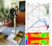
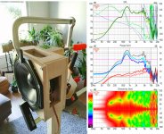
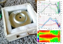
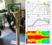
Simplified, the acoustic low pass filter is formed by the volume inside the box and the (combined) aperture at least. There is probably another low pass due to the basket but much higher in frequency. See responses of naked driver and driver with box with apertures without any damping at all to see the effect on post #185. I'll attach them here as well.
Introducing the box, without any damping whatsoever transforms the response of a naked driver dipole to something "cardioidish" least one octave lower, maybe two, so the low pass is working. High frequencies back side are reduced. When damping material is introduced the response doesn't change too much but the ripple is reduced. Although the measurements are not lab quality, the trend is there I think, this should be well above gate time of 3-4ms I used.
ps. I'm new to this too, just trying to interpret what I see here, pattern recognition and connecting the dots to reality with the help of emulating the system in simplified form.
Attachments are:
1. Naked driver, showing dipole response.
2. driver with enclosure making an acoustic low pass filter.
3. some damping material inside the enclosure, mainly reduces ripple and defines the pattern but not much change. Dipole below something like 700Hz.
4. pattern control to lower bandwidth is achieved by blocking half of the apertures lowering the low pass frequency
edit. Hmm, I've achieved "flat DI" with the small box with damping material, but the bandwidth is only on the upper spectrum >700Hz. Too much damping according to emulations.
Attachments
Last edited:

Hi Tmuikku,
Does this help? The front has been simulated as 2 sources since the front radiation is going to the rear via diffraction happens on both sides and I think that makes the difference.
Please go on.
Thanks and Regards,
WA
Does this help? The front has been simulated as 2 sources since the front radiation is going to the rear via diffraction happens on both sides and I think that makes the difference.
Please go on.
Thanks and Regards,
WA
Attachments
Last edited:
I think wonderfulaudio example is demonstrating diffraction using drivers as edges, X offset on the front and back drivers as perfect point sources?
Same can be done more accurately with the diffraction tool like in my emulation project. The front driver is diffraction tool simulated perfect radiator on same size baffle as the prototype box. The diffraction tool simulated measurements results include baffle edge diffraction, but do not include what effect sides and back of the speaker have. Nothing that happens after baffle edge is in the diffraction sim but neither is in the wonderfulaudio point source demonstration.
Anyway, what these sims represent is that no attenuation or delay is needed on the port output to achieve "cardioid" response. Can it be right since the resistance seems to be associated with this kind of projects? Whats going on, what wrong with the emulation, or is everyone talking about resistance for wrong reasons or what? Back to the the original question 😀
I make some more measurements one day, hopefully soon 🙂 I'll measure the prototype (which is the bigger volume box of the two measured in #185) without damping material and maybe some variations with damping, trying to have some inside back of the enclosure killing reflections there. Maybe elongate the box to get some path length around the back, if the varying the damping material doesn't reveal enough info. What should I try to get more sense to all this through measurements?
To avoid confusion I clarify that: there was two boxes measured on the post #185. When I've been talking about prototype lately I've ment the bigger box, which I never measured without damping material. Todays attachments are measurements of the smaller frame which is a bit shallower box with less volume while other dimensions and damping material are the same. All posted on the #185.
Last edited:
The answer has been written above a number of times. The delay needs to be close to the path length difference from the front to the cancelling source to get a cardioid pattern. This delay can come from various sources. Once you have it from one adding more from somewhere else will degrade the pattern.Anyway, what these sims represent is that no attenuation or delay is needed on the port output to achieve "cardioid" response. Can it be right since the resistance seems to be associated with this kind of projects? Whats going on, what wrong with the emulation, or is everyone talking about resistance for wrong reasons or what? Back to the the original question 😀
You are adding a low pass that includes delay in the filter. By picking the right filter you get the delay needed to generate the cardioid pattern. This is the fake part adding a specific low pass electrically when you are trying to represent an acoustic filter. The path lengths and properties of the damping material/port opening will determine the response of the low pass in the acoustic filter.
- Home
- Loudspeakers
- Multi-Way
- Resistive port cardioid active speaker insipired by D&D 8C