If you put the active drivers on the side it is much easier to extend the bandwidth of pattern control because to extend it higher needs less delay.
Have a look at this thread here and in the pages before where kimmo has given some good instructions on simulating active cardioids in vituix.
VituixCAD v2 - Page 5
There seems to be a lot of low frequency dipole in your results suggesting not enough flow resistance or too big ports, the box looks to be too leaky 😉
I don't know how to increase bandwidth control above the size of the driver, why would that be needed? if consistency is required maybe need to widen the response above that? Thanks for the link, Kimmos threads are so long it is hard to find the info!
edit.
Sorry, misunderstood your post or you edited it later 🙂
Yes drivers on the back is a good solution, free delay. If minimal delay is needed just put the holes near the driver.
Last edited:
Voodoo?
Ever heard of the boundary layer effect?
Plenty of information out there, so I have no idea what you're talking about.
Anyway, it's a common technique used in general acoustics.
Yeah it feels like voodoo 😀 I need to look for the info. Can't understand what resistance offers though since all we need is low pass filter and the aperture seems to do that already, what is the resistance needed for and what it does? Everybody talks about it and I don't get what it is.
Last edited:
Would a "box" like this be doable with a 15" midbassdriver like a td15m? If so, what frequency span would you think it could do? 80-200hz?
Gut feeling is that from about the wavelength of the driver diameter and couple octaves below so maybe ~200 - 800 Hz or so, you might get more accurate info by simulating or from the internets 🙂
Could you please indicate which measurement you talk about so I can learn from this new info? I wasn't concerned about the low frequency response of the 8", main goal was to have some pattern control, I expected the lows would be gone.
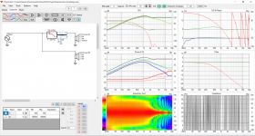
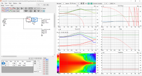
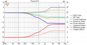
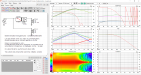
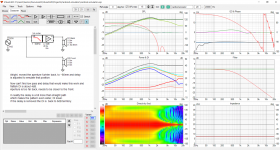
In this graph the DI on the right side is flat at about 5dB around 200 to 400.
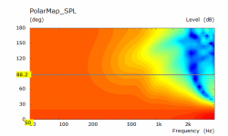
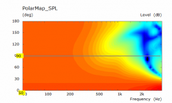
In both the output is lower at 90 degree off axis which is the dipole coming out. There needs to be some overlap in the directivity to get a smooth blend. The left graph has more dipole like response lower in frequency.
The low frequency output will be down due to the interference from the slots or side drivers creating the directivity but too much dipole won't help.
The depth of the enclosure matters too but Vituix won't simulate that. The resistive material causes the sound to be delayed and low passed in conjunction with the physical path length from the back of the cone through to the slots.Normal 8" driver would have DI near 0 at 400Hz already with minimal baffle. It looks like baffle of about 70cm x 70cm is needed to get some green color on the polar map on the side of 8" driver at 400Hz and mitigating the diffraction would need substantial roundovers. so, kind of confused what you refer to? I'm still not getting what the resistance is and how it affects?😀
Yeah it feels like voodoo 😀 I need to look for the info. Can't understand what it offers though since all we need is low pass filter and the aperture seems to do that already, what is the resistance needed for and what it does?
A good dose of skepticism is always good, but you're saying you're new to all of this, yet you already kind of judge some fundamentals in thermodynamics and acoustics as being voodoo? 🙄
Boundary layer effect is a fundamental part.
Often used in acoustics, but more often an unwanted side effect in all kinds of other fields of physics.
The point is, you won't get an easy answer, also not on the how much resistance part. The reason for that is that we move around the semi to completely nonlinear part of thermodynamics.
If you're lucky you will find some very complicated papers, probably with heaps of BEM/FEM approaches.
In general it's just a matter of trying things out, since that will probably cost you less time.
The reason why I mentioned it was not to give the best ever solution.
(since they don't exist in physics to begin with)
But to point towards techniques that might help and are at least worth investigating. Since the boundary layer effect is really effective on those lower frequencies.
Hehe, yeah little knowledge is dangerous, gives confidence that shouldn't be there 😀 Voodoo I call it since everyone seem to pass the subject around because it seems to be so complicated that computers are needed to solve it, hands in the air, only the lab men can do it in the company or university, without ever saying how it relates into this concept, pattern control of a loudspeaker? 😀
I know there is science behind all of it and boundary layer effect resonates my brain and your message about narrower slits would increase resistance because of it I understand. But what it is needed for here in this application? What is the outcome of resistance to the backwave, delay? This is what I haven't been able to figure out yet, what the resistance does to the polar pattern? Should I increase or decrease it for what? Can we just forget about the resistance since it doesn't seem to be needed here or can we? Simple holes with simple acoustic low pass formula seems to give close enough results that little bit of tuning with prototype will get seemingly good results without ever thinking about resistance. Thanks!
ps. is the resistance related to frequency dependent attenuation or delay? Can it be used for more consistent pattern? My examples have rising DI.
Last edited:
kimmosto made many cardioid protos, which have lately diappeared from his homepage.
I understand that stuffing leaking ports with cloth will basically attenuate high frequencies that would otherwise leak through ports with high energy (spl) = lowpass
I have made only couple of very poor cardioid mid protos (cloning Gradient Helsinki) but with so poor results that I abandoned that approach as a diy project. And I like dipole sound in the room so much that the decision holds still!
^ Yeah he did, looked them many times some years ago but don't remember much about it. I wish he posted them back online at some point 🙂 Otherwise we others need to generate new data. I need to look for more info on this, whitepapers and all. For now, I'm satisfied with the results.
The reason I'm questioning the importance of resistance for now in this application since I see no help for it with the simple VituixCAD emulation of cardioid speaker, which of course can be wrong and thus my observations would be wrong. Anyway, the emulation shows increasing attenuation, or delay, of the back wave doesn't benefit the pattern much at all, quite contrary. Helps with the bass but widens the pattern. To me it seems to be enough to control the low pass by aperture size and position and keep the attenuation and added delays and what not to minimum to get cardioidish pattern. I don't get what is the fuzz? If resistance increases delay, no need for it, less seems to be better. If resistance increases attenuation, no need for it, less seems to be better. What is it for, better keep it out from the system? 😀 alright, enough pollution from me for now, need to check the sims again with all this new influx of information 🙂
edit. Attachments, the emulation shows nice cardioidish flat DI response with only low pass and position of the back wave. If I add attenuation to it we have rising DI like in the real world examples. To get flat DI it seems attenuation on the back should be less, no resistance?
Attachments
Last edited:
paalj, thanks for the link! It is hard to remove stuff from the Internet 🙂
Yeah the measured pattern is probably influenced by the enclosure, my proto is lots smaller than 8c and port is closer to front so must be difference without even knowing whats inside.
The dipole pattern is just out of band, I used the results on the left of that image (8pr155) in the system, xo is about 300Hz where DI dips a bit. It was better match a bit higher up to DI of the woofer but the woofer box starts to have its own sound going on that high, it was designed for another system. I was happy when I saw the DI in the proto, pattern widens towards the woofer and narrows towards the treble which (sth100) also has rising DI and the result is smoothly rising DI without hickups. Not text book stuff with constant directivity but still a nice sound. DSP and c-c is tuned for smoothest DI and early reflections.
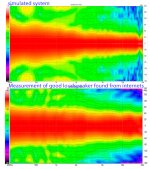
Anyway, found some measurements here Dutch & Dutch 8C Quasi-Anechoic Spinorama and Measurements | Audio Science Review (ASR) Forum . My system sim result is not nearly as perfect as 8c measurement but not that far away for a weekend experiment so gotta be happy!😀
I've been so excited about the new prototype it has been almost two years from previous one. Sorry being a bit arrogant today, hopefully I don't appear always like that 🙂 Loads of fun though, more smilies than usual.
Attached is VituixCAD project to test the simple cardioid emulation if anyone wants to tinker what lowpass, attenuation, delay and distance of the back side (Z) does. Try to get max attenuation to 180 degrees for cardioid. Widest bandwidth and highest DI seems to be found towards dipole / hyper cardioid stuff where strongest null is more to the side and some output at the back. Lots of stuff to think about, how to implement into a system, how to build etc. Tried to tinker with it and could find situation where delay or attenuation would help, maybe one or two db attenuation was helpfull to get the null exactly to the back side. Maybe the resistance stuff is relevant with cardioid subs?
In this graph the DI on the right side is flat at about 5dB around 200 to 400.
In both the output is lower at 90 degree off axis which is the dipole coming out. There needs to be some overlap in the directivity to get a smooth blend. The left graph has more dipole like response lower in frequency.
The low frequency output will be down due to the interference from the slots or side drivers creating the directivity but too much dipole won't help.
The depth of the enclosure matters too but Vituix won't simulate that. The resistive material causes the sound to be delayed and low passed in conjunction with the physical path length from the back of the cone through to the slots.
Yeah the measured pattern is probably influenced by the enclosure, my proto is lots smaller than 8c and port is closer to front so must be difference without even knowing whats inside.
The dipole pattern is just out of band, I used the results on the left of that image (8pr155) in the system, xo is about 300Hz where DI dips a bit. It was better match a bit higher up to DI of the woofer but the woofer box starts to have its own sound going on that high, it was designed for another system. I was happy when I saw the DI in the proto, pattern widens towards the woofer and narrows towards the treble which (sth100) also has rising DI and the result is smoothly rising DI without hickups. Not text book stuff with constant directivity but still a nice sound. DSP and c-c is tuned for smoothest DI and early reflections.
Anyway, found some measurements here Dutch & Dutch 8C Quasi-Anechoic Spinorama and Measurements | Audio Science Review (ASR) Forum . My system sim result is not nearly as perfect as 8c measurement but not that far away for a weekend experiment so gotta be happy!😀
I've been so excited about the new prototype it has been almost two years from previous one. Sorry being a bit arrogant today, hopefully I don't appear always like that 🙂 Loads of fun though, more smilies than usual.
Attached is VituixCAD project to test the simple cardioid emulation if anyone wants to tinker what lowpass, attenuation, delay and distance of the back side (Z) does. Try to get max attenuation to 180 degrees for cardioid. Widest bandwidth and highest DI seems to be found towards dipole / hyper cardioid stuff where strongest null is more to the side and some output at the back. Lots of stuff to think about, how to implement into a system, how to build etc. Tried to tinker with it and could find situation where delay or attenuation would help, maybe one or two db attenuation was helpfull to get the null exactly to the back side. Maybe the resistance stuff is relevant with cardioid subs?
Attachments
Last edited:
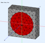
I have made some quick ABEC sims to show what happens with a change in depth for a flat piston roughly the same as you are using. Then these imported into vituix for a different view. Simulated between 50 and 4K so anything outside of that is made up data. There are gif's to make it easier to see the change. If you used a deeper cabinet and crossed slightly higher to the 15 you may have got a good rising DI too.Yeah the measured pattern is probably influenced by the enclosure, my proto is lots smaller than 8c and port is closer to front so must be difference without even knowing whats inside.
This shows what I said before that they start with 120 degree pattern that goes out to 180. Because of your waveguide you can't get the same but you did get a pretty smooth rising DI.Anyway, found some measurements ... My system sim result is not nearly as perfect as 8c measurement but not that far away for a weekend experiment so gotta be happy!😀
I've been so excited about the new prototype it has been almost two years from previous one. Sorry being a bit arrogant today, hopefully I don't appear always like that 🙂 Loads of fun though, more smilies than usual.
Excitement with a project is good 🙂
The z depth is 40mm which is why not much delay is needed and a 1st order low pass works. Once that gets up to 120mm which is more like the D&D then a second order filter or digital delay is needed. This is a good way of looking at how the options affect the pattern. The right delay changes for every driver and cabinet. Minimizing the depth is one way to reduce the need for much delay but it limits the options. There is no rocket science involved but finding the right mix to get the overall system response as desired will take some experimentation.Attached is VituixCAD project to test the simple cardioid emulation if anyone wants to tinker what lowpass, attenuation, delay and distance of the back side (Z) does. Try to get max attenuation to 180 degrees for cardioid. Widest bandwidth and highest DI seems to be found towards dipole / hyper cardioid stuff where strongest null is more to the side and some output at the back.
Attachments


Thanks for the sim fluid! For some reason I'm not following exactly what I'm looking at, is it closed box with different depths? DI is rising faster than what I'm used to see. Do you happen to have screenshot of the ABEC 3D view with the model to aid?🙂 Thanks!
I think the size of the driver goes hand in hand with size of the cabinet and delay belongs into the same soup as well meaning that for all 8" drivers there is one cabinet size and delay for same response in this application. Except the response looks a bit different due to structure of the driver and shape of the cone? but the main features remain the same I think because it is all about waves cancelling out = physical dimensions related to wavelengths. Is this what you are saying? Because ..
I'm not able to get any good response in the VituixCAD emulator with any amount of added delay or 2nd order filter for that matter. I think in this application the delay needs to be only so much that the shorter path length inside the enclosure is equalized to that on the outside, from a given point in the cone to the aperture. Outside the enclosure has a corner to go around, inside it is shorter path depending on the driver structure and cone shape and for full cancellation at the aperture they would need to be in opposite phase. Since the signals are already opposite phase in and outside when they are created only the path length needs to be compensated with added delay. For short path length difference, not much delay is needed. But, it is surpricing how much emulated delay in the VituixCAD changes the null angle at all frequencies.
In addition to this path length difference, there is two other phenomena happening outside that we need to compensate with the low pass filter inside. High frequencies beam and are thus attenuated at the aperture outside of the box and the baffle step transition is having some group delay below the beaming frequencies. We can emulate both on the backside with the low pass filter killing two flies with one trick? Where comes need for extra delay or attenuation in this application? The emulation does not show any advantage move ports too far away, or add any delay extra delay.
Only thing that is frequency dependent here is the baffle step and beaming, which are due to physical dimensions of the transducer and the enclosure and I think this is why the hole position doesn't matter much on the polar pattern frequency wise except for the path length difference in and out? With subwoofers there is no baffle step. How it is done then? I need to study this more, there is clearly a hole in the knowledge. This is more or less thinking and trying to remember what I've read during the years 😀
edit. wider baffle seems to yield stronger nulls on the back. With wider baffle the apertures need to be further back. Any delay or attenuation to the back seems to be as damaging (to the pattern) as with the narrow baffle. I think wider baffle helps to get cardioid lower. To avoid building roundovers and diffraction just use bigger woofer? Need to test in the evening.
The z depth is 40mm which is why not much delay is needed and a 1st order low pass works. Once that gets up to 120mm which is more like the D&D then a second order filter or digital delay is needed. This is a good way of looking at how the options affect the pattern. The right delay changes for every driver and cabinet. Minimizing the depth is one way to reduce the need for much delay but it limits the options. There is no rocket science involved but finding the right mix to get the overall system response as desired will take some experimentation.
I think the size of the driver goes hand in hand with size of the cabinet and delay belongs into the same soup as well meaning that for all 8" drivers there is one cabinet size and delay for same response in this application. Except the response looks a bit different due to structure of the driver and shape of the cone? but the main features remain the same I think because it is all about waves cancelling out = physical dimensions related to wavelengths. Is this what you are saying? Because ..
I'm not able to get any good response in the VituixCAD emulator with any amount of added delay or 2nd order filter for that matter. I think in this application the delay needs to be only so much that the shorter path length inside the enclosure is equalized to that on the outside, from a given point in the cone to the aperture. Outside the enclosure has a corner to go around, inside it is shorter path depending on the driver structure and cone shape and for full cancellation at the aperture they would need to be in opposite phase. Since the signals are already opposite phase in and outside when they are created only the path length needs to be compensated with added delay. For short path length difference, not much delay is needed. But, it is surpricing how much emulated delay in the VituixCAD changes the null angle at all frequencies.
In addition to this path length difference, there is two other phenomena happening outside that we need to compensate with the low pass filter inside. High frequencies beam and are thus attenuated at the aperture outside of the box and the baffle step transition is having some group delay below the beaming frequencies. We can emulate both on the backside with the low pass filter killing two flies with one trick? Where comes need for extra delay or attenuation in this application? The emulation does not show any advantage move ports too far away, or add any delay extra delay.
Only thing that is frequency dependent here is the baffle step and beaming, which are due to physical dimensions of the transducer and the enclosure and I think this is why the hole position doesn't matter much on the polar pattern frequency wise except for the path length difference in and out? With subwoofers there is no baffle step. How it is done then? I need to study this more, there is clearly a hole in the knowledge. This is more or less thinking and trying to remember what I've read during the years 😀
edit. wider baffle seems to yield stronger nulls on the back. With wider baffle the apertures need to be further back. Any delay or attenuation to the back seems to be as damaging (to the pattern) as with the narrow baffle. I think wider baffle helps to get cardioid lower. To avoid building roundovers and diffraction just use bigger woofer? Need to test in the evening.
Last edited:
Closed box flat piston, no lumped element script so just the inherent directivity of the piston and the box.Thanks for the sim fluid! For some reason I'm not following exactly what I'm looking at, is it closed box with different depths? DI is rising faster than what I'm used to see. Do you happen to have screenshot of the ABEC 3D view with the model to aid?🙂 Thanks!
In an active cardioid the delay of the filter or electronic delay needs to be close to the time of flight from the front driver to the cancelling driver. An acoustic one would follow the same principle.I think the size of the driver goes hand in hand with size of the cabinet and delay belongs into the same soup as well meaning that for all 8" drivers there is one cabinet size and delay for same response in this application. Except the response looks a bit different due to structure of the driver and shape of the cone? but the main features remain the same I think because it is all about waves cancelling out = physical dimensions related to wavelengths. Is this what you are saying?
Maybe this from Kimmo will help
GD ~ sound flying time from vertical center line of front baffle to center of side woofer + some extra because also box diffraction causes some LP causing extra GD.
In my example distance is 350 mm i.e. 1 ms. 10% more due to diffraction would be 1.1 ms. That happens with Bessel 12 LP @ 250 Hz.
I'm not able to get any good response in the VituixCAD emulator with any amount of added delay or 2nd order filter for that matter.
A Z depth of 40mm is impractical for an 8" driver as most are at least twice that deep already. This is a 15 on the front and a 5" driver on each side. No EQ to flatten the overall response but you can see the directivity.
Attachments

Thanks! I noticed too late the DI graph on your previous post has different scale than the default "sixpack", hense false notion of rapid DI rise... 😀
I think we have misunderstanding, I'm trying to emulate single driver passive cardioid two drivers in vituixCAD where the other driver emulates backside of the cone while the other is the frontside and Z approximates distance of the "aperture" from the front side. Add in some cm of delay to compensate the fact that in real world the backside of the cone is not at the aperture(s) but where the front side is. Main motivation for it was to study what happens if the backside, inside the box, is affected by the holes and damping material, acoustic low pass, some attenuation and some delay. Sorry for confusion!🙂
It might be better to emulate passive like you do with the active example, driver per aperture? Gotta try that as well to see how much different results it gives.
Last edited:
I think so, what you were simulating before isn't reality there is always going to be more path length than just the physical z distance, it's the acoustic path length difference between the front and cancelling source that matters and needs to be compensated in delay of some form.It might be better to emulate passive like you do with the active example, driver per aperture? Gotta try that as well to see how much different results it gives.
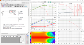
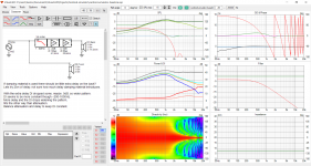
Here is bunch of tests that is another attempt to demonstrate the claims and clear any confusion there might be. To me it is clear as a day based on the few sims and proto boxes but I might be complete fool so after this post I go back to study. I would be glad to proven wrong since it is always opportunity to actually learn something so thanks for reading and commenting!🙂
The claim is that to get narrow pattern with passive cardioid like 8c (cardioid, supercardioid, what ever, narrower than omni) on mid range 2+ octaves below and up until 1kHz the aperture needs to be close to the front, attenuation and extra delay of the backside needs to be minimal and balanced and there has to be acoustic low pass filter.
Low pass on the back signal seems to be the only thing needed to get narrow pattern, any extra attenuation or delay of the back signal or the aperture too far back just widens the pattern and/or reduces the bandwidth = reduces the performance of what we are trying to achieve. Hense called resistance enclosure voodoo, because it looks like the resistance is not needed at all in this mid range application, only low pass is needed with ports not too far back from the driver. There really is nothing too complicated about this.
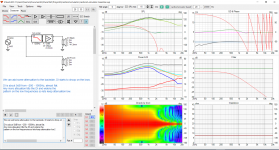
Some damping material seem to help reduce resonances and smoothen the response but too much and then there is too much attenuation and/or delay which reduces the performance. Low pass can be adjusted by the enclosure volume and aperture size, no resistance, voodoo or heavy science or even damping material is required 😀 Read attachments from left to right they visualize the claims.
The claim is that to get narrow pattern with passive cardioid like 8c (cardioid, supercardioid, what ever, narrower than omni) on mid range 2+ octaves below and up until 1kHz the aperture needs to be close to the front, attenuation and extra delay of the backside needs to be minimal and balanced and there has to be acoustic low pass filter.
Low pass on the back signal seems to be the only thing needed to get narrow pattern, any extra attenuation or delay of the back signal or the aperture too far back just widens the pattern and/or reduces the bandwidth = reduces the performance of what we are trying to achieve. Hense called resistance enclosure voodoo, because it looks like the resistance is not needed at all in this mid range application, only low pass is needed with ports not too far back from the driver. There really is nothing too complicated about this.
Some damping material seem to help reduce resonances and smoothen the response but too much and then there is too much attenuation and/or delay which reduces the performance. Low pass can be adjusted by the enclosure volume and aperture size, no resistance, voodoo or heavy science or even damping material is required 😀 Read attachments from left to right they visualize the claims.
Attachments
I think so, what you were simulating before isn't reality there is always going to be more path length than just the physical z distance, it's the acoustic path length difference between the front and cancelling source that matters and needs to be compensated in delay of some form.
Check out the demonstrations above, this doesn't matter regarding the sims since sims showed any additional delay worsens the performance. Hense, best possible real world situation is without any extra delay. Any extra delay due to resistance or damping or physical dimensions on the back wave seems to be bad for the performance and logic from that says there is no possibility or opportunity to compensate with delay in this application. The little compensation there needs to be done due to inside/outside path length difference is by position of the aperture from the front (Z). There is probably optimum depending on the driver structure, but it is going to be close to the front. Otherwise, avoid adding any delay to the back besides the low pass.
Forgot to write the motivation for the claims. This was just a quick study how to make such enclosure and simplify the info so anyone can try it. I'm not too good at simplifying though, took zillion posts and tons of confusion already 🙂
Last edited:
In the simulation the low pass has delay from the filters group delay. If you were to make your low pass linear phase you would see that you need to add some electronic delay to get back to where you were.Low pass on the back signal seems to be the only thing needed to get narrow pattern, any extra attenuation or delay of the back signal or the aperture too far back just widens the pattern and/or reduces the bandwidth = reduces the performance of what we are trying to achieve. Hense called resistance enclosure voodoo, because it looks like the resistance is not needed at all in this mid range application, only low pass is needed with ports not too far back from the driver. There really is nothing too complicated about this.
The group delay of the filter, electronic delay or acoustic path length delay through the ports needs to match the front to back distance from the centre of the cone to the exit of the port. Different types and amounts of material will change this.any extra delay from an simplified ideal I used just widens the response = reduces performance. Hense claim that any extra delay due to resistance or material or physical dimensions on the back wave is bad for the performance. As I see it there is no possibility or opportunity to compensate with delay in this application, delay reduces performance.
In your proto the port is very close to the driver so there needs to be hardly any resistance or material for it to match. A bigger driver, more baffle width or port being further back would change that.
Good point of view! One probably wants some attenuation on the box due to resonances. For repeatability use some consistent material like insulation sheet. I have no idea what is the delay with such material, if it slows speed of sound by half the delay is about the thickness of the material so the required delay is probably in few centimeters. To compensate for the delay the baffle needs to be wider and port further back to increase path length outside more than inside (unless slanted sides).
To maximise the path length difference use equal sided straight angle triangle as guide. If the delay of the material was 2cm, the path lenght ouside needs to be 2 cm longer than inside, the baffle needs to be ~5cm wider than the driver and the port corresponding amount back from the front. Shortest path length difference is with minimal baffle and port right at the driver rim like I have in the proto. So the next proto, with same damping material, should be a bit wider and the aperture same amount back. Need to find out what is the resistance of the material I'm using to calculate optimal baffle width, nice. But it is flushmount and roundovers to mitigate diffraction problems... well, we are ready for extra work for better sound quality aren't we? Actually, heavy damping inside (back of) the enclosure and light damping on the ports would reduce resonance a lot while still less delay and attenuation for the direct back signal to the apertures, maybe allowing for narrow baffle and skip roundovers and flushmounting, need to test this.
ps. If the logic is correct delay of 8c apertures (damping material) can be calculated from the aperture distance to the edge. The woofer is recessed in the baffle to further increase path length difference.
edit. math 😀
Last edited:
At least in the USA, getting a patent isn't too hard, but protecting it or having it be really valid might be. It often comes down to who has the best team of lawyers to intimidate the other side from going to court.
The really good ideas are tightly held if possible to keep them out of the public realm.
I have a pair of Dahlquist DQ16 speakers here that use a panel of urethane foam edge-glued into the cabinet about midway in the volume. There is a port as well towards the bottom.
I haven’t torn it apart to see how thick, and dense/open/closed cell the foam is however. I discovered this while attempting to have a look at the crossovers.
These are great sounding speakers that my wife had purchased while working at Magnolia Hi-Fi many years ago, and I don’t want to alter them, so haven’t dug any further than just poking around through the hole made for the terminal plate.
- Home
- Loudspeakers
- Multi-Way
- Resistive port cardioid active speaker insipired by D&D 8C