It can work very well, but it is also difficult to do. That's probably why you see what you see.
You have to run the woofer right on the edge to cross to a waveguide. You have to know where that is, you have to build the right waveguide to work with it, you need to know how to blend them and what to reject.
There is much good information on the 'Geddes on Waveguides' thread. It may take a while to read.
Hey Allan,
thank you for helping me out with these beginner's questions, appreciated. Do you know of any focus points within the Geddes mega-thread? (it is lengthy) I think I remember that Geddes' Abbey speakers were intended to be used with subs, which would make them, strictly speaking, a 3-way system, right?
Could my confusion stem from different goals of factions within DIY audio? I understand that the original Econowave people actually intended an affordable CD-speaker, so there is probably a build in compromise, which is the midrange performane. If I get it right, Geddes use of CD is to reduce early reflections which improves the stereo illusion, but he also uses subs to support them in the low region and this helps with the upper midrange reproduction, reducing strain on the woofer. Then the Econowave people looked to Wayne Parnhem, he did not use subs and also crossed the 15" woofers betwen 1.3 to 1.6 kHz, which should be rather high and the woofer was also working all the way down. What trade-offs are accepted here? What can be expected from a 12" woofer running that high, technically speaking and also what will be audible?
Troels, who uses a 12" in a 3-way speaker crossed it at 500 Hz, which cannot be reached with a 1" compression driver and waveguide. This, because upper midrange, in his view, should not be the labour of a 12" woofer. But in a 3-way system, they thrive, he thinks. What do the big companies do, which this 2-way design leans on?
The retro line of JBL, the 4429 and the 4349 both feature much more sophisticated 12" woofers than the ones available on the market and in my pricerange. I suppose any comparison with those designs must take this into account, that it is not possible to reach their level of optimization. The 4429 is a 3-way system and can cross the woofer at 800 Hz, uses a waveguide for the midrange and a super tweeter. The waveguides discussed here cannot really reach this low, they will loose directivity around 1 kHz. But would this be an option, to find a 2" CD driver and try to cross lower? The 4349 then again crosses at 1.5 kHz, but they also use some advanced technology. Probably even the old 4425 could technologically be more optimized for a 2 cft. enclosure than the combination of a Eminence 3012LF and a B&C DE250?
What can I say, that thread took years to digest as well as to write. I'll try to break down some of what you ask...
Dr Geddes doesn't cross his woofers at the low end, not the 8", the 12" or the 15". They overlap with the subs. The excursion isn't the issue, it's the breakup behaviour. The woofer has to be used to its upper limit to be useful in this kind of cross.
By the way, I've used the DE250 to 500Hz. I prefer not to, but I found nothing specifically wrong with it.
A late addition to my questions: What was your procedure to figure out the crossover with real components? I have decided on the enclosure sizing now and the choice of the woofer will only be a question of compromises. After I found the proper crossover frequency (as low as possible above 1 kHz, 1.1 to 1.2 I figure), I need to check out the audible reality and inevitably change the components in this course.@Shepple:
You'll have to do a hell of a job with finding the right frequency to crossover.
How to do it? 1) Buy cheap components and later make the real thing from better parts? 2) Get lower-than-simulated component values so that I can make incremental changes by adding small values in series? And so on.
I wonder what good practice looks like after simulation. What was your experience?
I've bought lots of capacitors during past 15 years and have aquired about 20 inductors of different values. I have two Jantzen donuts that i use if i need large values with low dcr and i wind them to the value i need. I also make my own aircore coils. I have about 700 Philips MKC 1uF/100V that i use to make any value i need for testing and a bag full of Russian PIO and Wima ranging from 10-100uF. In adition to that i have about 100 resistors of different values to combine. When i look at my component box, it costed arround 100€ or so but for me it is priceless for doing necessary test crossovers.
In your case, if you are not willing to make speaker building a hobby - for capacitors i'd use elco bipolar for test crossovers. F&T are quite good and inexpensive. Buy some 1uF foil caps for bypassing elcos. If you like the sound with them, you'll love it with mkp caps.
If you need large value caps for a notch filter that is low in frequency, feel free to use polarized elcos connected back to back (- on - in series). If you need 500uF on notch filter for woofer, just buy 1000uF/100V polarized elcos and connect them in series to get bipolar around 500uF. You usualy have to add something to parallel on top of those two to get to the desired value. ESR and ESL are irrelevant in that configuration so there is no need for expensive caps there.
Regular 10W ceramic resistors are cheap so just buy 4x33, 4x22, 4x10, 4x4.7, 4x3.3 and 12x1 ohm. Combining them in serial or parallel you can get almost any value you want.
For coils of large values i'd advise you to buy Dayton laminated from Soundimports shop. For lower mH values you could wind your own or just buy Intertechnik air coils.
Always use Rdc of coils in parallel in your simulations. In many cases it will show that there is no need for low Rdc coil and you will save money that way. Especially in parallel with tweeters or in series notch filters where you almost always have to put some resistor in line with cap and an inductor.
This maybe looks a bit scary but more than once i've made the crossover point where i think it should be but it turns out that it sounds better bellow or above that point in listening tests. Measurably, you would thought it was the same speaker.
The better your initial measurements are, the better job crossover simulator will do. These days when i measure, i do this:
photographer photographed — Postimages
None of this will be possible without at least Dayton dats.
Last edited:
I'm not sure it's necessary.None of this will be possible without at least Dayton dats.
Hah.. Touché ")
Well, you do need to check and measure values of your capacitors and coils you wind. When using elco caps, usually tolerances are 10% . That's how i got 450uF elco bipolar instead 500uF that really needed to be that value.
When i said your comment is vague, what i meant was - give a man counter suggestion instead of just bein' "it is not necessary". Explain him what to do, how and in what conditions. That way you'll add some weight to it.
Hey Zvu,
great reply, this perfectly makes sense to me and I have some imagination now: Get myself a collection of components first. Also when I consider my headache when I was sitting in front of the simulator, dealing with the phase correction, I wasn't sure if this could ever be solved without a considerable amount of passive parts at hand, trying things out. Which leads me to the idea to sell my pre and poweramp and buy two Hypex FA122 instead. I got to admit, all these coils, caps and all of this numbers and units are so very intriguing, it really comes at you. But then again I only need to crossover two drivers, active should be fine.
Nice hat Allen
Hey Zvu,
great reply, this perfectly makes sense to me and I have some imagination now: Get myself a collection of components first. Also when I consider my headache when I was sitting in front of the simulator, dealing with the phase correction, I wasn't sure if this could ever be solved without a considerable amount of passive parts at hand, trying things out. Which leads me to the idea to sell my pre and poweramp and buy two Hypex FA122 instead. I got to admit, all these coils, caps and all of this numbers and units are so very intriguing, it really comes at you. But then again I only need to crossover two drivers, active should be fine.
Nice hat Allen
Hypex is a great solution. I'm sure you'll be happy.
One thing though. You are making high eff two way so you might have to use some passive attenuation for tweeter. Given that it is about 107dB raw, you don't want to destroy S/N ratio. I'd also advise a largish capacitor in series with tweeter - for safety reasons. JBL M2 uses about 30uF if i'm not mistaken, but you check at LH forum anyway.
Last edited:
I've found it on my drive.

Yes, MKP is good enough. Value is largish so it doesn't influence their tweeter lower end response given that it is crossed at 750Hz.
Since you already need to do some serious thinking on how will you do the measurements to get quasi anechoic with gate at least 8ms long - when you have those, you'll be able to simulate the effect of such a simple 6dB crossover and attenuation fairly easy.
Last edited:
I was hoping this would get me somewhere if I walked down that line Testing Loudspeakers: Which Measurements Matter, Part 1 | audioXpressI've found it on my drive.
Since you already need to do some serious thinking on how will you do the measurements to get quasi anechoic with gate at least 8ms long ...
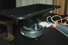
Lately I was in doubt whether it was too smart to ditch the Dayton PH6512 JBL-clone Progressive Transition waveguide for an exponential horn. I almost wanted to get myself a CNC'd custom-build done but that is probably rather dumb. But when I departed from the JBL-clone Dayton, it was because of the ditch in the lower frequencies and there was the assumption it could be caused by the straight tubing of the screw-on. Now when I was searching the Google image search for the older, bigger PT-F95HF I found someone over at the audioroundtable forum who actually sawed-off the thread-on section (image attached). Can this improve the performance? I was wondering whether JBL would not have optimised the waveguide for the thread-on section an its removal cause more problems than benefits. Anyway it is tempting.
Attachments
Last edited:
I finally found out the reason why ...
In short, Geddes had to say the following:
And now what EarlK said ealier in this thread here:
My question to the experienced is: If the JBL (clones) is only a diffraction horn and it features considerable resonance, how does the Emimence H290B compare? As an exponential horn it does seem to be much smoother, no resonances there. What is the trade-off? What is it's defficit?
It is all resonance. Zilch actually got Earl Geddes to meassure the smaller, thread-on JBL waveguide, and it happened here at diyaudio: Horn vs. Waveguide Just out of curiosity I would appreciate if someone has the summarized findings file that he offered for download on his website but that is not online anymore, as mentioned in thread where the meassuring originated B&C Compression Driver and Horns It should follow the name "Horn VS waveguide.pdf"... that JBL waveguide produces it's own roller-coaster ( peaks + dales ) to the response ( I think due to the reflective knuckles built into it's expansion profile ).
In short, Geddes had to say the following:
Per an agreement that I made from another thread, I received, measured, and evaluated a very inexpensive JBL horn ... .
As I said before, this is not a waveguide, it is a diffraction horn. It acts just like every other diffraction horn that I have measured and nothing about the measurements that I got surprised me.
And now what EarlK said ealier in this thread here:
Lots of people like the sound of these // and that's what's important ( at the end of the day ).
My question to the experienced is: If the JBL (clones) is only a diffraction horn and it features considerable resonance, how does the Emimence H290B compare? As an exponential horn it does seem to be much smoother, no resonances there. What is the trade-off? What is it's defficit?
It could be easy to answer this, but really so much depends on the parameters of the horn with regards to how you implement it and how you use it.
Generally speaking an exponential doesn't have constant directivity. It is difficult to use near its cutoff, and it is awkward to terminate.
It is rarely chosen for higher frequency domestic duty, but its modern equivalent, the LeCleach horn is more popular.
Generally speaking an exponential doesn't have constant directivity. It is difficult to use near its cutoff, and it is awkward to terminate.
It is rarely chosen for higher frequency domestic duty, but its modern equivalent, the LeCleach horn is more popular.
As I meant to say, since directivity varies much depends on how (for example where in frequency) you use it.
Resonances, some of them can be equalised and they are not a sign you have a bad horn. Sometimes an exponential has good looking measurements because of its curves.
Even odd kinds of horn can sound good, but when you have heard a little better you know why.
Resonances, some of them can be equalised and they are not a sign you have a bad horn. Sometimes an exponential has good looking measurements because of its curves.
Even odd kinds of horn can sound good, but when you have heard a little better you know why.
The H290B is different than a usual exponential horn in that it uses an oblate spheroidal / elliptic cylindrical flare profile in both the horizontal and vertical planes, with a mouth radius borrowed from LeCleach.I understand. How did Wayne Parham got the H290B to work so well then with his designs? His directivity meassurements always looked quite good. Is this specific exponential horn different?
Wayne explains here:
AudioRoundTable.com: Pi Speakers >> H290C Horn/Waveguide
Having also built plywood horns during 2011 using a similar quadratic throat waveguide approach, can say they do sound very good, even if mine didn't measure quite as well ;^).
Art
Last edited:
- Status
- This old topic is closed. If you want to reopen this topic, contact a moderator using the "Report Post" button.
- Home
- Loudspeakers
- Multi-Way
- B&C DE-250 FRD & ZMA questions