For a slightly higher DI -
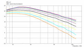
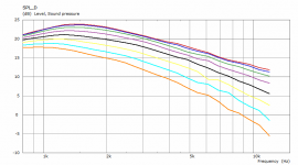
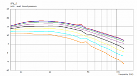
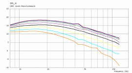
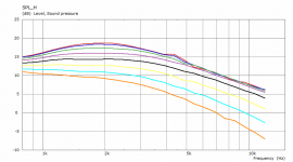
It's actually better on diagonal (SPL_D chart). This is 14" wide, 1.4" throat. The cyan line is for 45° off axis (7.5° step).
Dmitrij_S - good points, I suppose.
It's actually better on diagonal (SPL_D chart). This is 14" wide, 1.4" throat. The cyan line is for 45° off axis (7.5° step).
Dmitrij_S - good points, I suppose.
Attachments
Last edited:
It is actually about 90° coverage nominally (the first one).A flatter waveguide is always going to be smoother, but with less DI control. As the DI gets raised there will be more problems. ...
Will try to test a bigger one with 1" throat.
Last edited:
This is also funny: Today, solely by mistake, I tried something I didn't want (what could be considered as an error), but hey, the result is one of the best I have seen -
Now I know how to improve things!
There you go
I suppose, revolutionary improvement would mean
* Flat acoustic loading from 200-300Hz and up to the last audio octave (e.g. like Heavise or step Sigmoid function).
* Constant directivity in the same frequency range. (I suppose beamwidth of -+(20-30)° in all directions would be ok, at least for home audio).
*Horn-related acoustic nonlinearities would be comparable to that of the direct radiator.
*Perhaps, some kind of numerical criterion should specify a minimum value of HOMs amount.
"Revolutionary design" should improve all the point above at the same time. But as we know, "the horn reality" is completely different. Numerical optimisation helps to find a certain balance of contradictory horn parameters
You mention 4, of which I came up with 3 myself.
Now some of Einstein's quotes would be appropriate, but redundant.
Last edited:
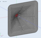
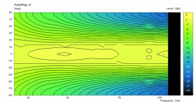
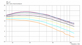
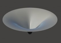
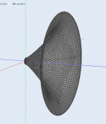
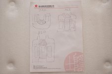
So, this is 16.1" x 15.5" horn, 1" throat. There are obviously some wiggles from the analysis as this was still only a coarse setting. Otherwise pretty good, isn't it.
Again, cyan line is for 45° off-axis.
Again, cyan line is for 45° off-axis.
Attachments

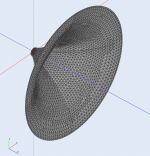
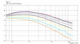
The same for a circular one (16.2") - there is a very slight narrowing just below and around 2 kHz compared to the rectangular one.
Attachments
Last edited:


It probably isn't serious but it isn't nice either. This is what striked me the most - how perfect is the rectangular one in this regard. Not seen so often.
The parameters are the same. I'm not sure about the effects on different shapes.
The parameters are the same. I'm not sure about the effects on different shapes.
No, this is a different one, about 16" across. Matching in size the one before.Is the pure OS wg the "old one" (52cm Ø)?
Last edited:
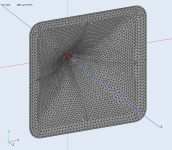
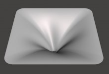
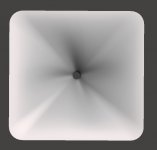
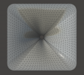
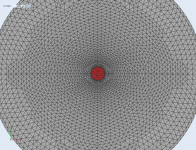
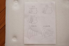
Basically what is done here are protrusions and grooves made in the surface but not in a symmetric manner. When you directly compare the pure OS (on the left) and the one with grooves, the latter is a bit better. Not a huge effect but definitely in the right direction.
Attachments

Last edited:
* Flat acoustic loading from 200-300Hz and up to the last audio octave (e.g. like Heavise or step Sigmoid function).
* Constant directivity in the same frequency range. (I suppose beamwidth of -+(20-30)° in all directions would be ok, at least for home audio).
*Horn-related acoustic nonlinearities would be comparable to that of the direct radiator.
*Perhaps, some kind of numerical criterion should specify a minimum value of HOMs amount.
My comments would be (in order)
* since loading is almost irrelevant to performance, I don't see this as very important.
* this is achievable now with a no-compromise design. Its the size and other details which when compromised create the performance degradation.
* since the acoustic nonlinearities in the waveguide are insignificant, this isn't very important.
* as the design becomes less diffraction oriented, the driver dominates the generation of HOMs. Hence, this is not really an aspect of the waveguide that is of concern. It is, of course, a big concern in waveguides where HOM generation is not taken into consideration, but for the "perfect" device we are talking about, the HOM generation in the waveguide is dwarfed by that generated by the driver.
Basically what is done here are protrusions and grooves made in the surface but not in a symmetric manner. When you directly compare the pure OS (on the left) and the one with grooves, the latter is a bit better. Not a huge effect but definitely in the right direction.
Honestly, I don't see much difference since you say that the small glitch at 4.5 kHz is numerical (which seems right to me as it looks like a single point.)
Last edited:
As the design becomes less diffraction oriented, the driver dominates the generation of HOMs. Hence, this is not really an aspect of the waveguide that is of concern. It is, of course, a big concern in waveguides where HOM generation is not taken into consideration, but for the "perfect" device we are talking about, the HOM generation in the waveguide is dwarfed by that generated by the driver.
So far I have only seen one (exotic) manufacturer, or rather his son, who seems to have taken this into account when developing custom driver / horn combinations. These are clearly modern revisions to Salmon horns and companion drivers, but an interview with the guy revealed that he extensively modeled, simulated and optimized the drivers (phase plugs) and horn interface(s) in COMSOL in order to suppress the modes.
Attachments
Last edited:
- Home
- Loudspeakers
- Multi-Way
- Acoustic Horn Design – The Easy Way (Ath4)