I know atleast 3 diefferent experimental studies of sub-harmonics in compression drivers
Jerry Hubbard from Altec Lansing
Subharmonic and Nonharmonic Distortions Generated by High Frequency Compression Drivers
Fernando Bolanos from Beyma (the study has comprehensive reference list )
Measurement and Analysis of Subharmonics and Other Distortions in Compression Drivers
and both theroetical and experimental study by Alexander Voishvillo for JBL
Comparative Analysis of Nonlinear Distortion in Compression Drivers and Horns
As Earl Geddes already mentioned, sub-harmonics arises from parametric/autoparametric modulation of the system parameters (capacity, stiffness, mass, etc.).
As follows from the study of Alexander Voishvillo, there are at least 3 potential source of sub-harmonics related to the compression chamber (3 column)

Fernando Bolanos (and other researchers reffered in his study) believed that an important cause of the subharmonic and other nonharmonic distortions in CD could be related to the diaphragm resonances. Interesting experimental results are reported.
And I will just quote Conclusion from Jerry Hubbard study
Jerry Hubbard from Altec Lansing
Subharmonic and Nonharmonic Distortions Generated by High Frequency Compression Drivers
Fernando Bolanos from Beyma (the study has comprehensive reference list )
Measurement and Analysis of Subharmonics and Other Distortions in Compression Drivers
and both theroetical and experimental study by Alexander Voishvillo for JBL
Comparative Analysis of Nonlinear Distortion in Compression Drivers and Horns
As Earl Geddes already mentioned, sub-harmonics arises from parametric/autoparametric modulation of the system parameters (capacity, stiffness, mass, etc.).
As follows from the study of Alexander Voishvillo, there are at least 3 potential source of sub-harmonics related to the compression chamber (3 column)
Fernando Bolanos (and other researchers reffered in his study) believed that an important cause of the subharmonic and other nonharmonic distortions in CD could be related to the diaphragm resonances. Interesting experimental results are reported.
And I will just quote Conclusion from Jerry Hubbard study
The performance of a high frequency compression driver is a
blend of several parameters affecting efficiency, bandwidth,
power output, and distortion. This report dealt with two of the
more unusual kinds of distortion found in compression drivers
widely used in professional audio. It is important to note that
all of the drivers tested showed some level of subharmonic or
nonharmonic distortion. In several cases, the magnitude of these
distortions was found to be significant, even at modest input
power levels. It was suggested that the causes of these
distortions were particular modes of vibration of the dome or
nonlinearities of the compliance that were best suited to
analysis using laser imaging techniques.
The loudspeaker designer, faced with making the best
performance compromises, must carefully choose the components of
a driver's moving system. The size and shape of the dome, the
mass, strength, internal damping, and fatigue resistance of the
diaphragm material, and the compliance stiffness and geometry are
all factors which contribute to the design of a satisfactory
product.
Last edited:
Your welcome.
That disertation seems to have missed my patents on phase plug design, that's disappointing since there is a lot of good info in those patents, including a critical analysis of Smith's work. As a Professor I am very passionate about literature searches. When good material is missed, you have to wonder how much else was missed.
Coincidentally, I reread your patent today and it occurred to me that the SEOS waveguides have a lot in common with (the transition of) your round to rectangular phase plug design.
Last edited:
I know atleast 3 diefferent experimental studies of sub-harmonics in compression drivers
As Earl Geddes already mentioned, sub-harmonics arises from parametric/autoparametric modulation of the system parameters (capacity, stiffness, mass, etc.).
As follows from the study of Alexander Voishvillo, there are at least 3 potential source of sub-harmonics related to the compression chamber (3 column)
Fernando Bolanos (and other researchers reffered in his study) believed that an important cause of the subharmonic and other nonharmonic distortions in CD could be related to the diaphragm resonances. Interesting experimental results are reported.
That's relevant research Dmitrij, thank you for posting it.
In the interview with the ESD guy, he specifically referred to most of the sources mentioned in Voishvillo's table.
ESD uses huge magnets of an exotic material (I believe it's a Cobalt-iron similar to Permendur) in combination with field coils. Diaphragms are custom made TruExtent/Materion.
Last edited:
From what I've read it seems unlikely that subharmonics should be an issue in a home environment listening music, but that is of course only my impression. I wonder if one gets a compression driver on a test bench, how to decide if the driver is good enough or not. If it is a real (i.e. occuring and audible) problem even at home levels, seems still quite under the radar.
The only lesson I got so far is that it is better to avoid large diaphragm drivers with wild break-ups but that is a sensible approach even without knowing that subharmonics exist.
The only lesson I got so far is that it is better to avoid large diaphragm drivers with wild break-ups but that is a sensible approach even without knowing that subharmonics exist.
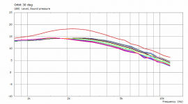
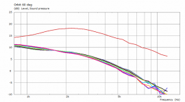
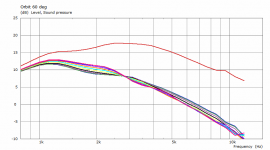
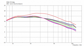
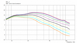
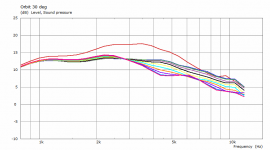
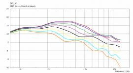
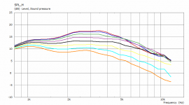
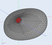
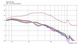
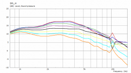
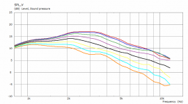
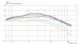
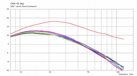
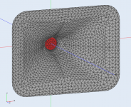
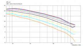
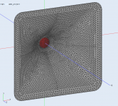
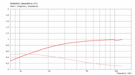
And as a reminder of what influence a good termination has -To get more perspective, this is for a small elliptical waveguide (8.5" x 6") -
(BTW, this will be a good demo project - calculates in less then a minute.)
Attachments
Of course it depends also on the horn. Both should match and there are several ways of how to do it. It also depends on what overall DI you would aim at.In a two-way design, with an 800hz crossover, would a 15" have a better directivity transition to a horn than a 12" driver? Or does that depend on the directivity of the horn at the 800hz crossover?
A slightly more refined mesh with more frequency points, 20 minutes. Oh, these numeric glitches are annoying (I have a suspition about the subdomain interface shape playing a role)...
Attachments
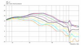
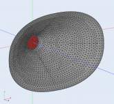
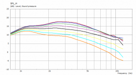
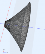
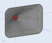
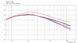
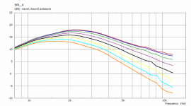
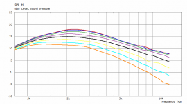
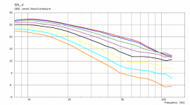
The same shape (with the same abrupt termination), only morphed to a rectangular outline of the same width and height -
Attachments
Last edited:
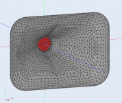
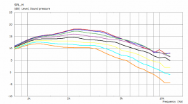
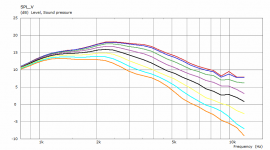
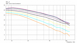
Finally, a better mouth termination added back. Now this is extremely clean. Compare it to the original purely (super)elliptic here.
Attachments
Last edited:
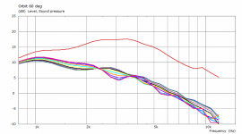
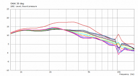
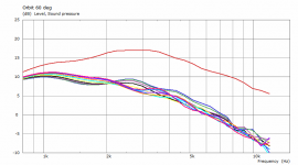
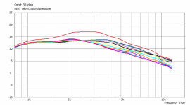
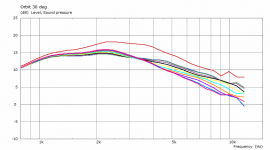
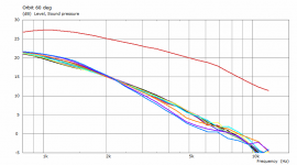
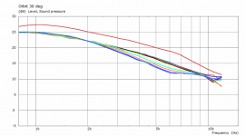
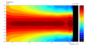
Is that pattern flip in the orbit 30deg image around 3khz, where the lines flip order?
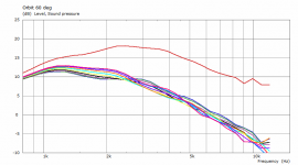
Rectangular waveguides seem a lot better than round, it is cool to see these graphs and compare. Altough, round is easier to make without cnc/3d printing.
ps. could you share abec simulation related setting of the 16"+ waveguide you posted recently? I'm getting errors if I try to simulate bigger ones as I posted in this thread some time ago. Thanks!
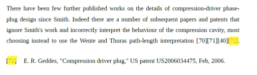
Jack Oclee-Brown in his doctoral thesis mentions one of your patents but also states that it is wrong... That disertation seems to have missed my patents on phase plug design, that's disappointing since there is a lot of good info in those patents, including a critical analysis of Smith's work. As a Professor I am very passionate about literature searches. When good material is missed, you have to wonder how much else was missed.
") (page 114)
(page 114)Honestly, I don't know for sure what he means but maybe you could spare a few words (?). Or do I read it wrong?
Attachments
Last edited:
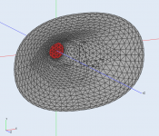
This is for a 50 mm dome (vibrating axially) in a conical throat -
tmuikku - I'll get back to you.
tmuikku - I'll get back to you.
Attachments
- Home
- Loudspeakers
- Multi-Way
- Acoustic Horn Design – The Easy Way (Ath4)