
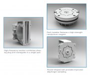
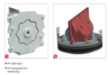
Here's the driver with "flower-shaped" exit and the phase plug of the JBL line array waveguide. These are parts of the VTX A12.
Attachments
Last edited:
Would it be possible to get other than quarter-space symmetry? Let's say you make the 5-pointed horn you show, then you could use 1/10-space symmetry.Superformula!
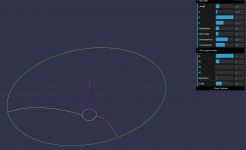
OK, now the fun may begin. So far the only shape-curve (see the documentation) available was a superellipse. From now on it is possible to define a superformula (see wikipedia).
See also Example 22 | Superformula Shape | Super-formula Plotter for examples of various shapes - you will need to understand this.
The definition in the script file looks like this (the numbers for SF are: a, b, m, n1, n2, n3):
ShapeCurve = SF
SF = 2,1,4,8,12,12
SF.Rot = 0
The absolute size of the shape-curve is computed from Coverage_Horizontal and Depth.ConicSectionPart. This sets the width of the shape curve which is scaled so that just fits this dimension. Parameter SF.Rot gives an arbitrary rotation of the mouth if needed. Attached are two demo scripts. The only limitation for now is that for ABEC simulation you need quarter-space symmetry. I yet have to implement full mesh export (and it will take a heck of a time to run those sims). Eventually you can still use the "raw2rect" parameter to make the mouth rectangular (and force the symmetry where it makes sense).
The download: www.at-horns.eu/release/ath-4.4.1.zip
/Anton
")
I have a feeling I can do something like this now too. The ceiling type horn. Just working out the math and scaling. I can just about move the throat around in 3D space so the wg and sf curves still work.
https://www.diyaudio.com/forums/multi-way/338806-acoustic-horn-design-easy-ath4-82.html#post6052077
https://www.diyaudio.com/forums/multi-way/338806-acoustic-horn-design-easy-ath4-82.html#post6052077
Last edited:
....and I don't buy the "lower is better" crossover ideas that seem to abound...
Hi Earl,
I think that idea comes from the notion that no crossover is better than a crossover, so let's minimize the use of crossovers in the range of highest human sensitivity to flaws, which is apparently in the 1000-3000 or 750-4000 Hz range.
Many speakers have a crossover near 2000 Hz, so it was seen as an issue worth addressing.
Do you see anything wrong or irrelevant with that idea?
cheers
Arg
I agree that there should be no crossover between 800 and more like 6000, and IMO there should be no crossover above 800 Hz. That was a fundamental rule in my designs. But I see people compromising on this idea to get down to 500 Hz or lower, and that IMO is not worth the inevitable crossover above 800 Hz. Better to move up the 800 Hz. - but no more than absolutely necessary - than use another higher crossover. Going to 2k is a very bad idea however as that is right in the most audible range.
Going bigger with the waveguide (lower control) and smaller with the compression driver (more HF output) allows for this to be done.
Going bigger with the waveguide (lower control) and smaller with the compression driver (more HF output) allows for this to be done.
Last edited:
Well, the steeper the crossover slope(s), the more precisely must the individual radiation patterns below and above the crossover point match - this is what you should be looking for then. Frankly, I'm not a fan of very high slopes, 24 dB/octave is about my reasonable limit. I know that nowadays with DSP it is no problem to make it steeper but I don't really see the point - I don't see a broader overlap necessarily as a bad thing.
I agree that there should be no crossover between 800 and more like 6000, and IMO there should be no crossover above 800 Hz. That was a fundamental rule in my designs. But I see people compromising on this idea to get down to 500 Hz or lower, and that IMO is not worth the inevitable crossover above 800 Hz. Better to move up the 800 Hz. - but no more than absolutely necessary - than use another higher crossover. Going to 2k is a very bad idea however as that is right in the most audible range.
Going bigger with the waveguide (lower control) and smaller with the compression driver (more HF output) allows for this to be done.
Thanks Earl. It seems we are in agreement after all, in principle.
Although as a matter of detail, human sensitivity to crossovers can't drop from high at 800 Hz to nothing at 500 Hz. I would expect that there would still be benefits to pushing it down below 800 Hz. But not if it means a crossover being added at the high end, 5 kHz or less: I agree with you there.
cheers
Well, the steeper the crossover slope(s), the more precisely must the individual radiation patterns below and above the crossover point match - this is what you should be looking for then. Frankly, I'm not a fan of very high slopes, 24 dB/octave is about my reasonable limit. I know that nowadays with DSP it is no problem to make it steeper but I don't really see the point - I don't see a broader overlap necessarily as a bad thing.
I agree, I think very steep crossovers are a bad idea. My system was 3rd order LP and first order HP, although that is misleading since the waveguide response is not flat so there is also a first order HP at 10 kHz as well.
Thanks Earl. It seems we are in agreement after all, in principle.
Although as a matter of detail, human sensitivity to crossovers can't drop from high at 800 Hz to nothing at 500 Hz. I would expect that there would still be benefits to pushing it down below 800 Hz. But not if it means a crossover being added at the high end, 5 kHz or less: I agree with you there.
cheers
I had designs for s system that could go down lower, probably 500 Hz, but the costs just got in the way. It needs to be much larger with an 18" woofer and would have raised the price by probably 50% over the NS15. Not worth it IMO.
In fact, when I look back on "value" (performance / cost) the 12" was the sweat spot. But the 15" was a little better, just cost a lot more.
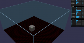
Well - setting up the 'test room'. Can drag the enclosure around the room and up and down the walls too.
Working on
i). moving horn throat position in 3D space
ii). update Mabat profile curves accordingly
iii). box radius/chamfer
iv). port hextreme
v). physics stuff
Working on
i). moving horn throat position in 3D space
ii). update Mabat profile curves accordingly
iii). box radius/chamfer
iv). port hextreme
v). physics stuff
Attachments
Last edited:
CD1.5NR1P, maybe?
http://www.precision-devices.com/file-downloads/PrecisionDevices-PD-CD1.5NR1PDatasheet290419.pdf
http://www.precision-devices.com/file-downloads/PrecisionDevices-PD-CD1.5NR1PDatasheet290419.pdf
Last edited:
Well, the steeper the crossover slope(s), the more precisely must the individual radiation patterns below and above the crossover point match - this is what you should be looking for then. Frankly, I'm not a fan of very high slopes, 24 dB/octave is about my reasonable limit. I know that nowadays with DSP it is no problem to make it steeper but I don't really see the point - I don't see a broader overlap necessarily as a bad thing.
I've been having what I believe are very good results using steep xovers.
Don't have much theory or simulation experience to back this up, I just take a lot of measurements.
I always use linear phase xovers, Linkwitz-Riley or any other fully complementary xover, and then vary the xover freq and order as I make polar measurements looking for even patterning.
So far, on typical off the shelf horns for 1.4" CDs and a few synergy attempts, steep has given better vertical polars.
Steep has also allowed me a bit more latitude in choosing xover freq, not having to worry about lower excursion issues, and being able to focus more on pattern exchange.
All this has been with a fairly narrow build formula however, CD to 12" or 12"s in the 500Hz to 700Hz range
(I use 12" because I need big subbage and 15"s are too little to works as subs, and for other supposed theoretical advantages, like staying pistonic etc.)
- Home
- Loudspeakers
- Multi-Way
- Acoustic Horn Design – The Easy Way (Ath4)