That worked!
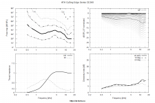
Also, here's how a dome tweeter performs in a waveguide based off of the CE360 model. (This isn't CE360, it's smaller.)
Looking pretty good...
Here's the model, as of now. Still needs some tweaking:
Throat.Profile = 1
Throat.Diameter = 34 ; [mm]
Throat.Angle = 15 ; [deg]
Coverage.Angle = 50
Length = 76.2
Rollback = 1
Rollback.StartAt = 0.585
Rollback.Angle = 180
Rollback.Exp = 1.5
OS.k = 1.30
Rot = 3.26
Term.n = 4.03
Term.q = 0.996
Term.s = 1.32
Source.Contours = {
zoff -2
point p1 4.68 0 2
point p2 0 14 0.5
point p3 1 15 0.5
point p4 0 16 0.5
point p5 0 17 1
cpoint c1 -18.59 0
cpoint c2 0 15
arc p1 c1 p2 1.0
arc p2 c2 p3 0.75
arc p3 c2 p4 0.25
line p4 p5 0
line p5 WG0 0
}
; -------------------------------------------------------
Mesh.AngularSegments = 32
Mesh.LengthSegments = 60
Mesh.SubdomainSlices=
Mesh.WallThickness = 6
Mesh.ThroatResolution = 4.0 ; [mm]
Mesh.InterfaceResolution = 12.0 ; [mm]
; Mesh.InterfaceOffset = 5.0 ; [mm]
; -------------------------------------------------------
ABEC.SimType = 2
ABEC.f1 = 500 ; [Hz]
ABEC.f2 = 16000 ; [Hz]
ABEC.SimProfile = 0
ABEC.NumFrequencies = 61
ABEC.MeshFrequency = 30000 ; [Hz]
ABEC.Polars:SPL = {
MapAngleRange = 0,90,19
Distance = 2 ; [m]
}
Report = {
Title = "ATH Cutting Edge Series CE360"
Width = 1200
Height = 800
NormAngle = 0
}
; -------------------------------------------------------
Output.SubDir = "demos"
Output.STL = 1
Output.ABECProject = 1
Attachments
That's solely up to the user, it's possible to create abrupt terminations as well (not that it brings any advantage).
My imprecision. The OS-SE formula was implemented with termination in mind, its application is up to the user. The more surface is used in termination, the pattern control will diminish, while frequency linear distortion optimized.
Will you introduce the feature of a virtual enclosure into Ath some time, mabat?
Regards
I found a fork of PrusaSlicer called Superslicer, which has improved thin wall capabilities, for those who want to print single walls.
Releases * supermerill/SuperSlicer * GitHub
Releases * supermerill/SuperSlicer * GitHub
The more surface is used in termination, the pattern control will diminish, while frequency linear distortion optimized.
This a very good way of putting it and is the reason why I lean towards larger waveguides.
We can simulate these things and perhaps could derive the actual source shape from measured results, based on the differences from the sims.
Haven't we gone over this several times. Of course, you can do that, even with far field data. It's just a lot of math from here to there, not excluding the construction.
Take a simple idea; place the driver flush in an infinite plane. You know exactly what its radiation pattern has to be for a flat shape wavefront at the exit aperture. Any deviations are due to curvature, which can be separated out by ...
I wonder if the problem could be that we go from one phase plug into another in a pretty short distance
The 2021 Klipsch Jubilee uses a Celestion Axi2050 with their K-693 designation. In this video:
CES2021 Klipsch Jubilee with Roy Delgado - YouTube
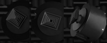
It includes an animation of what Roy Delgado calls an additional “extended wide dispersion phase plug” that was to fit inside the rectangular throat of the K-402 horn. The 5 part phase plug looked like miniature nested versions of the K-402.
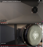
Klipsch dealer Cory Harrison of Paducah Home Theater posted November 7 2021 a new Jubilee using the K-693, but a completely different phase plug with five rings behind the 2” horn entrance:
The Biggest. The Baddest. The Jubilee. First Look! - YouTube
At about 5:30 minutes in Cory talks about the “straight up” Celestion Axi2050 driver used, however not exactly the same, mainly because of the (5 ring) phase plug, “it’s a 50 cent part ..where all the magic is” increasing the high frequency (snare drum..) coverage to 80 or 90 degrees compared to the 50-60 degrees the B&C DE75 (a 2” exit 3” titanium diaphragm/mylar surround driver) used in the older Jubilee had.
The Axi250 phase plug has only three portions, do you think the 5 ring Klipsch plug could be nested in the stock plug, or would require further modifications?
Art
Attachments
Last edited:
This time I meant specifically an option of measuring it more directly, without all the modal maths (which should be not that hard in theory, it's just a bit cumbersome). Some means of separating and "amplifing" little areas of the wavefront into larger portions of air where it could be easily measured and then the wavefront simply reconstructed.Haven't we gone over this several times. ...
Last edited:
Mabat,How is it supposed to work? It seems unlikely to me that it does what is claimed.
The "vanes" on the rectangular director animation posted in #8946 appear to be around a wavelength long at the VHF where the K-402 horn dispersion starts to narrow. Many manufacturers have used something similar to spread out VHF to "fill" the outer portion of straight sided horns, somewhat similar to sections of multi-cell horns.
The circular "phase plug" appears like it's vanes would be too short to re-direct VHF, unless by diffraction.
Are diffraction effects included in your simulations?
Art
Last edited:
Yes, they are.Are diffraction effects included in your simulations?
Perhaps for the purpose of the external phase plug optimization it would suffice simply to measure the outputs of the channels individually (with other channels damped). One could get relative amplitude and delay/phase of each input ring, which seems all that's needed.... Some means of separating and "amplifing" little areas of the wavefront into larger portions of air where it could be easily measured and then the wavefront simply reconstructed.
This could give an easy mapping of the measured pressures to the wavefront shape (with some knowledge what the measured pressure in each channel shoud be for an ideal wavefront). Any flaws in my reasoning?
Maybe the position of the mic could be fixed in some distance in front of the plug, instead of the pictured position.
Attachments
Last edited:
Hmm, I don't know how about the damped channels (I would guess that not much) but the open channels certainly will affect the output, as the sound waves from each channel can propagate freely and interfere once they leave the plug interior. I'd be afraid this can induce too much mess into the data.
Is the timing enough to go by on its own, because that wouldn't change by blocking things off, so would show up a non-flat wavefront from the entry.
You know that the amplitudes will be correct as long as the entering wavefront is the expected one. So either it is or it isn't.
You know that the amplitudes will be correct as long as the entering wavefront is the expected one. So either it is or it isn't.
If the plug was made 100 mm (4") long, I could get at least 0.5 ms of reflection free time, during which none of this can have any effect (I could even simply close off the channels without any damping). Since all of this will be HF stuff, maybe even 0.5 ms would be enough (frequency resolution could suffer though).
Last edited:
mabat,
two questions:

two questions:
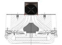
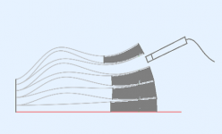
1) Is it possible to "cut" only the two sides of an existing axisymmetrical waveguide using the guiding curve, leaving the rest of the waveguide as is? If yes, can you give a hint what is to be done?
2) Can I define the morph of the waveguide to only work at this sides, so that it despite being a shorter curve now reach a flush level? If yes, can you give a hint what is to be done?
Simple use case is fitting a lager waveguide on a smaller baffle:
No, that's not possible at the moment. I thought about importing an arbitrary user-defined GCurve (that would be the black line in your picture) but then I would need to implement some sharp corner detection, etc. - quite complex extension.
But what's the difference if you make it rectangular instead? It would be almost the same.
But what's the difference if you make it rectangular instead? It would be almost the same.
- Home
- Loudspeakers
- Multi-Way
- Acoustic Horn Design – The Easy Way (Ath4)