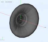
Says wall thicknes .8mm
you can do that with FDM too
Or even smaller, if you manage a .2mm extruder
you can do that with FDM too
Or even smaller, if you manage a .2mm extruder
How can the shipping be so cheap? I sent a small block of foam from Mich. to Calif. and the costs were $80 - $140.
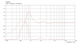
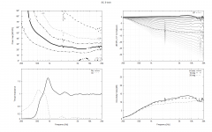
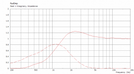
Red - Axi2050 in free air
Blue - Axi2050 in the horn with phaseplug from yesterday
Both are on axis measured at 1m
As I look at these results, I have to believe that they confirm what I expected. The wavefronts in the channels are going to be perturbed by the lateral acceleration necessary for them to stay in the channel. This will clearly have an effect on the wave impedance of the channel with each channel different. I don't see how they can ever sum coherently at HFs. To me any attempt to cause the wavefront to move in a manner contrary to what the physics say, will have this problem. Only when the wavefront is allowed to expand as the physics say it should will this problem not occur.
They have the right account with the right shipper and enough volume of business to warrant it. It is the same way that Amazon can ship anything next day for nothing or a 50 cent item can be posted from China for free when the item costs less than the cost of a stamp in any other country.How can the shipping be so cheap? I sent a small block of foam from Mich. to Calif. and the costs were $80 - $140.
That is the on-axis response that suffers from effects of axisymmetric diffractions, very much the same way as e.g. a suboptimally terminated OS waveguide. As aragorus also showed (#8694) at 15 deg off axis this already disappears. It's obvious that the tested waveguide is not properly matched to the phase plug so there will be a lot of secondary radiation at the outer edge of the plug. It's too early to make any conclusions, IMO. It would be good to have a full polar set to see the whole picture.As I look at these results, I have to believe that they confirm what I expected. The wavefronts in the channels are going to be perturbed by the lateral acceleration necessary for them to stay in the channel. This will clearly have an effect on the wave impedance of the channel with each channel different. I don't see how they can ever sum coherently at HFs. To me any attempt to cause the wavefront to move in a manner contrary to what the physics say, will have this problem. Only when the wavefront is allowed to expand as the physics say it should will this problem not occur.
Let's not forget that this is fed by a 2" throat and the exit diameter of the plug is around 4" - and at least up to 10 kHz this is without a hint of beaming or a noticeable diffraction so far. To me this is already a remarkable result.
Last edited:
2pc of ST-260 to Sweden...
87€
//
Btw - I just checked out the costs - did not order it - yet 🙂
//
I agree with Mabat.
The results I showed are far from perfect.
Next week I'll make a pair of horns that match the phase plug better and file the edges of the meanders to reduce reflection.
It would be nice to make a rectangular plug, however I agree that it would be hard to anticipate how the impedance will be seen at the eges of the rectangular shape, since they are longest from the center and the area expansion is the highest snd thus the vanes need to get more thin.
Maybe it could work if the vanes are divided are separated by supports in the corners...
Or develop them as 4 seperate channels 2 horizontal and 2 vertical for each "ring"
That is the on-axis response that suffers from effects of axisymmetric diffractions ...
This isn't true, asymmetrical diffraction will also affect the off-axis response. Agreed that its effect on-axis is large, but off-axis is also affected.
up to 10 kHz this is without a hint of ... a noticeable diffraction so far.
I would also not agree with this.
Last edited:
Sure, and that's the difference between "suffer" and "be affected".This isn't true, asymmetrical diffraction will also affect the off-axis response. Agreed that its effect on-axis is large, but off-axis is also affected.
OK, here we don't agree. Remember your arguments 🙂
- This is a BEM simulation of what is aragorus testing (driven with a flat wavefront). To me the question is how close can we get with a real implementation & construction. I don't see a fundamental theoretical problem - wouldn't it show already in the simulations?
Attachments
Last edited:
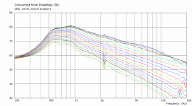
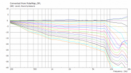
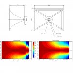
Here's the "standard" report. It's already a pretty complex model so it's not easy to get it all clean but if we reached that performance at least up to 12 kHz with a 2" throat, that would be just awesome. (The waveguide is still without any serious optimization.)
BTW, the 5-vane version could probably improve it further in the top octave.
BTW, the 5-vane version could probably improve it further in the top octave.
Attachments
Last edited:
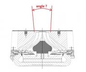
I would think that since the driver exit is 12 degrees, the wavefront isn't exactly flat... or am I wrong?
The siimulation doesn't look that bad...
I wonder if the problem could be that we go from one phase plug into another in a pretty short distance
The siimulation doesn't look that bad...
I wonder if the problem could be that we go from one phase plug into another in a pretty short distance
Attachments
Last edited:
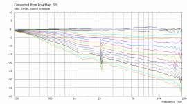
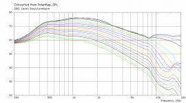
To put things into perspective, this is what happens if "the wavefront is allowed to expand as the physics say it should" - an OSWG with a 2" throat (ø486 x 150 mm).
Can we improve it above 8 kHz with the spherical wavefront plug? I believe we can.
Can we improve it above 8 kHz with the spherical wavefront plug? I believe we can.
Attachments
It dosn't sound that nice when you move 30 cm in either direction 😀
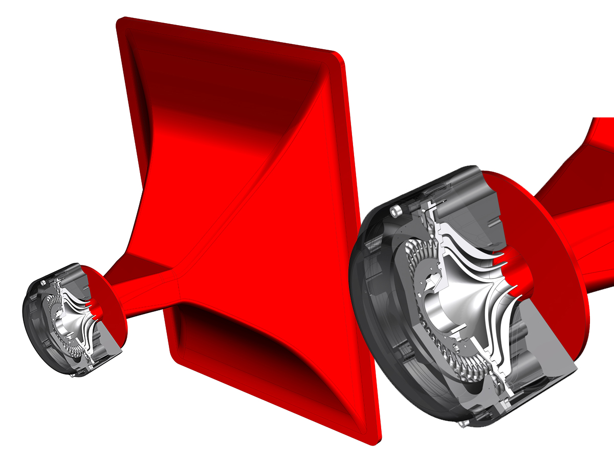
The red horn that the Axi driver was advertised with is a diffraction horn
The red horn that the Axi driver was advertised with is a diffraction horn
Attachments
Last edited:
That's one of the reasons I would try to insert the (dampened) tube segment between the two.I wonder if the problem could be that we go from one phase plug into another in a pretty short distance
I'm still not sure what's the best way to proceed in a case where there's a conical exit in the driver. A dampened straight tube directly from the exit of the phase-plug could be one solution.
Last edited:
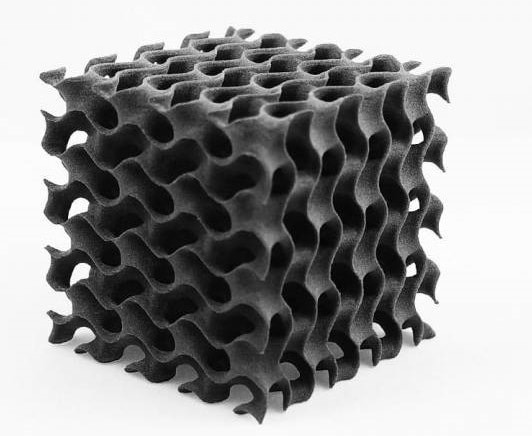
I'll try to measure what some tiny gyroid infill does to the performance. Maybe it could be incorporated inside of the plug
Attachments

It dosn't sound that nice when you move 30 cm in either direction 😀
The red horn that the Axi driver was advertised with is a diffraction horn
My photos from Frankfurt Messe don’t appear to be easy to dig out of my backups, but I didn’t remember it being a diffraction slot at the throat.
Here's a press release of that horn, with some good photos:
Celestion Features Big Red Horn for Axi2050 Axiperiodic Driver at Prolight+Sound 2019 | audioXpress
As Celestion engineers explain, the company created a bespoke horn specifically designed to work with and optimize the wide bandwidth performance of the Axi2050. The uniquely designed “Big Red Horn” that appears at Prolight+Sound 2019 has been constructed using a distinctive fibreglass compound in Celestion red (other colors are available!) — features a 2-inch throat exit with a 90x45 degree radiation pattern and 400Hz cut-off frequency
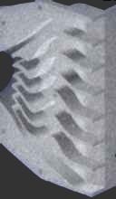
This is another bit of 'prior art' that I finally remembered the source of. It's from an EV X-Line, I believe:

Edit: found a better one:

Attachments
Last edited:
- Home
- Loudspeakers
- Multi-Way
- Acoustic Horn Design – The Easy Way (Ath4)