Thanks Earl,
I can't wait to see how all Mabat's and others' horn designs, along with 3d printing pans out.
Like said, please gimme some flat outer walls to mount to (that aren't too dang curved and thick).
Want a horn that works all the way down!")
Thank you Ro808,
Yep, horizontal secondary has to more pronounced if H>V.
Just the nature of tying the main horn aspect ratio together, with the secondary flares.
I can't wait to see how all Mabat's and others' horn designs, along with 3d printing pans out.
Like said, please gimme some flat outer walls to mount to (that aren't too dang curved and thick).
Want a horn that works all the way down!
Thank you Ro808,
Yep, horizontal secondary has to more pronounced if H>V.
Just the nature of tying the main horn aspect ratio together, with the secondary flares.
Now if you folks will just please get these awesome designs going where we can mount some dang cones onto their sides....
Like said, please gimme some flat outer walls to mount to (that aren't too dang curved and thick).
Want a horn that works all the way down!
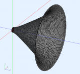
I already tried to give you something as flat on the edges as I could, but even this is going to be hard to fabricate without a CNC
Any of the designs can be made flat on the back with a bit of CAD effort and making the horn as big as you can live with does give more room to make the mid areas flatter without affecting the response too much. That horn shown is 658mm H x 872mm W.
Attachments
Last edited:
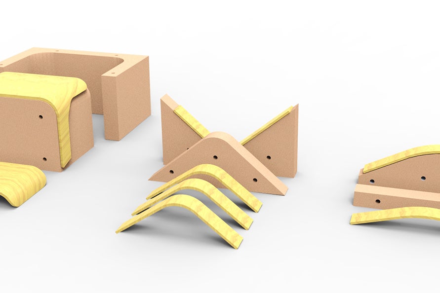
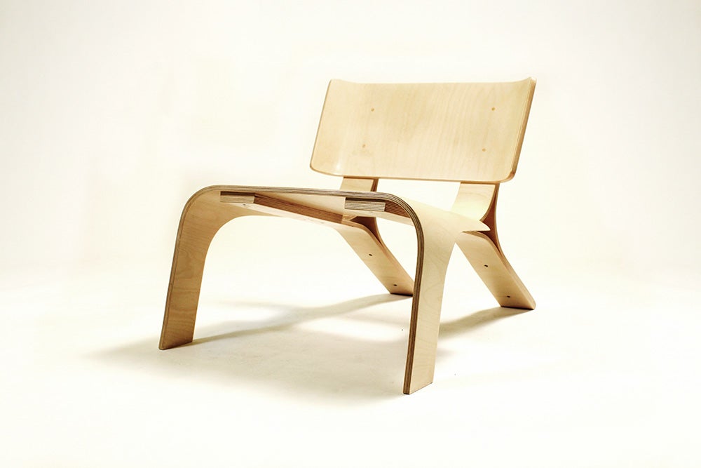
One way to make such a horn is to either print, or even better: CNC the throat + the first few inches of the horn out of a solid piece of (stacked) plywood.
The remaining (large) parts of the horn section could be laminated by glueing thin (precidely cut) sheets of plywood that are placed into a mold, which are then clamped together.
You basically need to prepare only 1 mold for a symmetrical horn, or 2 for different H and V angles.
Here's an example of a plywood chair.
Last edited:
The throat area is where smooth transitions are most important, which is why printing or CNC is almost mandatory for non-axisymmetrical horns.
CNC milling the continuous curves of large horn walls can quickly become very expensive, so laminating them makes sense. Obviously, you can only laminate curves in one direction.
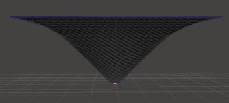
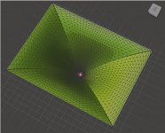
The construction of a mold can be simplified by attaching different 'profiles' at an appropriate distance to a surface. The mold doesn't need to provide the full contour. As long as you have enough structural elements in your mold to guarantee that curve, you don't even need a top piece for the plywood to be bent to.
I think this and my previous post belong in this thread
CNC milling the continuous curves of large horn walls can quickly become very expensive, so laminating them makes sense. Obviously, you can only laminate curves in one direction.
The construction of a mold can be simplified by attaching different 'profiles' at an appropriate distance to a surface. The mold doesn't need to provide the full contour. As long as you have enough structural elements in your mold to guarantee that curve, you don't even need a top piece for the plywood to be bent to.
I think this and my previous post belong in this thread
Last edited:
That is possible but in some places the curves are compound so a simple bending jig wouldn't work. You could come quite close with some design modifications to make it more easily fabricated by that method.The remaining (large) parts of the horn section could be laminated by glueing thin (precidely cut) sheets of plywood that are placed into a mold, which are then clamped together.
Given the trials Mark had making his foam secondary flares when he has a good workshop and skill level he might not be keen to step up to compound plywood bending and laminating
Making a mold out of foam and then laying fibreglass on in would probably make more sense if a full on CNC horn is out of the question. If you have a machine MDF is cheap if you have to pay someone to make it then the cost will be high.
Mabat did make another thread to discuss practical approaches to construction so this probably should continue there rather than here.
Last edited:

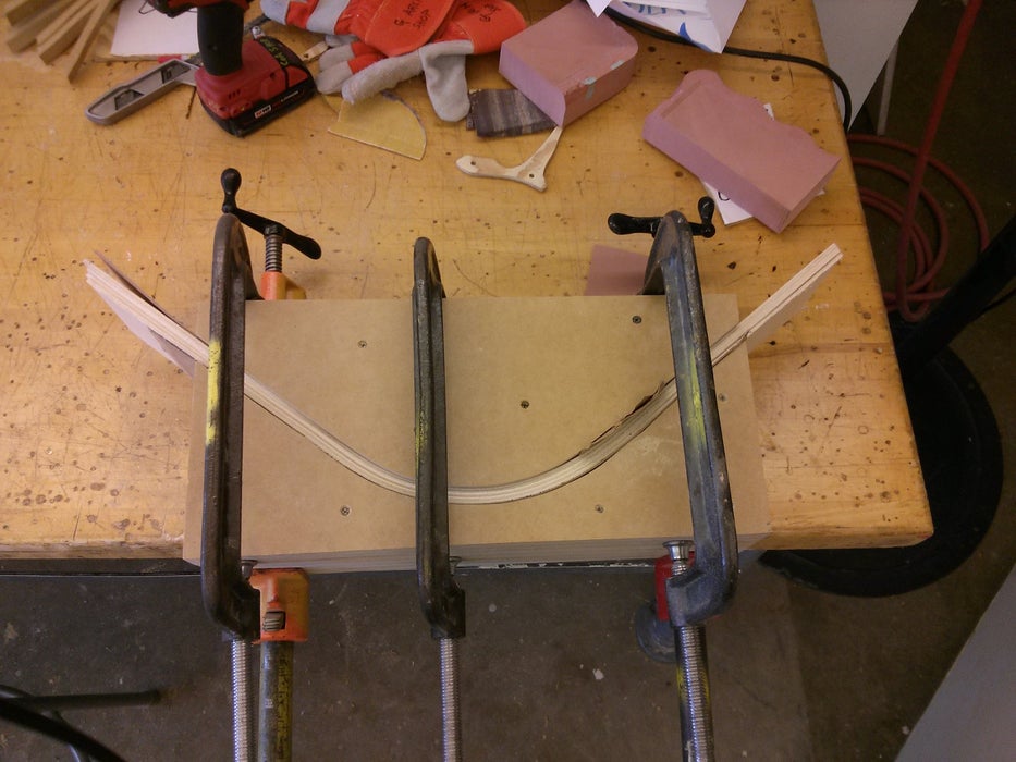
Alternative to laminating would be kerf bending Already tried long kerfs with a track saw and it seems work fine, all ~50 cuts similar to each other. Kerf bending requires a jig to bend against so not sure if it is any easier than laminating.
Does anyone know a trick or plugin or something how to get cut sheet for bent panels? In other words, If I model such a horn that could be made with 4 bent plywood pieces, how to cut the correct size pieces?
Already tried long kerfs with a track saw and it seems work fine, all ~50 cuts similar to each other. Kerf bending requires a jig to bend against so not sure if it is any easier than laminating.Does anyone know a trick or plugin or something how to get cut sheet for bent panels? In other words, If I model such a horn that could be made with 4 bent plywood pieces, how to cut the correct size pieces?
I think it has been covered pretty well in the meantime. The aspect ratio alone is not the limiting factor - as was mentioned, it's also the overall size and the required bandwidth at the same time. Anyway, I would always try for the lowest aspect ratio, i.e. to make it more like square if possible (ratios around 1.2 work quite well for me) - I simply don't see the benefit of more rectangular shapes. I do see an acoustic advantage of a square over a circle however.Mabat, in your estimation, what is the aspect ratio we need to stay under to avoid pattern flip?
I think i recall Tom D as having said 1.6x is about the upper limit. And i assume that he was talking about his straight-walled conical synergy horns probably including secondary flares.
My synergy efforts at 1.5x measure with some flip, albeit mild enough to easily live with.
Very interested in your take for your far more sophisticated horns...thx.
Last edited:
Does anyone know a trick or plugin or something how to get cut sheet for bent panels? In other words, If I model such a horn that could be made with 4 bent plywood pieces, how to cut the correct size pieces?
Solidworks can only flatten surface not plate (have not tried metal sheet module). Blender maybe?
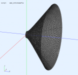
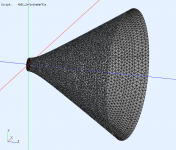
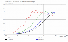
Here is the project file in case anyone would want to try various mouth terminations to see the effect:
Geometry.Definition = 2
Throat.Profile = 1
Throat.Diameter = 25.4 ; [mm]
Throat.Angle = 0 ; [deg]
GCurve.Type = 1
GCurve.Width = 254
GCurve.SE.n = 2
Length = 200 ; [mm]
Term.s = 0.0
Term.n = 4.0
Term.q = 0.996
; -------------------------------------------------------
; Mesh Setting
; -------------------------------------------------------
; ABEC
Mesh.AngularSegments = 100
Mesh.LengthSegments = 20
Mesh.ThroatResolution = 4.0 ; [mm]
Mesh.InterfaceResolution = 7.0 ; [mm]
Mesh.InterfaceOffset = 5.0 ; [mm]
Mesh.ZMapPoints=0.5,0.2,0.7,0.7
; -------------------------------------------------------
; ABEC Project Setting
; -------------------------------------------------------
ABEC.SimType = 1
ABEC.f1 = 800 ; [Hz]
ABEC.f2 = 10000 ; [Hz]
ABEC.NumFrequencies = 40
ABEC.MeshFrequency = 1000 ; [Hz]
ABEC.Polars.Dist = 2.5 ; [m]
ABEC.Polars.Step = 7.5 ; [deg]
ABEC.Polars.Points = 8
ABEC.Polars.Horizontal = 1
ABEC.Polars.Vertical = 0
ABEC.Polars.Diagonal = 0
ABEC.Polars.DiagonalInclination = 0.0
ABEC.Polars.PMapNorm = 20
; -------------------------------------------------------
; Output
; -------------------------------------------------------
;Output.DestDir =
Output.STL = 1
Output.MSH = 0
Output.ABECProject = 1
Output.Coords = 0
If someone wants to sim a big waveguide, this one's 63.3 cm Ø.
Changing the coverage (half) angle to 40 results in 569.7 mm (22.429") Ø.
Geometry.Definition = 1
Throat.Profile = 1
Throat.Diameter = 25.4 ; [mm]
Throat.Angle = 15.5 ; [deg]
Coverage.Angle = 45
Length = 200 ; [mm]
Term.s = 0.8
Term.n = 4.0
Term.q = 0.998
Morph.TargetShape = 0
Rollback = 1.8
Rollback.StartAt = 0.8
Rollback.Rate = 0.08
; -------------------------------------------------------
; Mesh Setting
; -------------------------------------------------------
Mesh.AngularSegments = 64
Mesh.LengthSegments = 20
Mesh.ThroatResolution = 4.0 ; [mm]
Mesh.InterfaceResolution = 8.0 ; [mm]
Mesh.RearShape = 1
Mesh.RearResolution = 10.0; [mm]
Mesh.WallThickness = 5.0; [mm]
Mesh.ExteriorSegments = 0
Mesh.InterfaceOffset = 12.0 ; [mm]
; -------------------------------------------------------
; ABEC Project Setting
; -------------------------------------------------------
ABEC.SimType = 2
ABEC.f1 = 1000 ; [Hz]
ABEC.f2 = 10000 ; [Hz]
ABEC.NumFrequencies = 20
ABEC.MeshFrequency = 1000 ; [Hz]
ABEC.Polars.Dist = 2.5 ; [m]
ABEC.Polars.Step = 7.5 ; [deg]
ABEC.Polars.Points = 8
ABEC.Polars.Horizontal = 1
ABEC.Polars.Vertical = 0
ABEC.Polars.Diagonal = 0
ABEC.Polars.DiagonalInclination = 0.0
ABEC.Polars.PMapNorm = 20
; -------------------------------------------------------
; Output
; -------------------------------------------------------
Output.DestDir = "C:\Horns\Demos" ; current directory by default
Output.STL = 1
Output.MSH = 0
Output.ABECProject = 1
Output.Coords = 0
Attachments
Last edited:
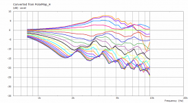
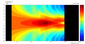
... and now with a smooth termination added, two cases for s=0.25 and s=0.5 (length 200 mm and coverage angle 64.5 deg fixed):Not that it is any interesting but this is the polar map for the longest one, i.e. ⌀254 x 200 mm. Of course this is not how to do it
Attachments
- Home
- Loudspeakers
- Multi-Way
- Acoustic Horn Design – The Easy Way (Ath4)