")
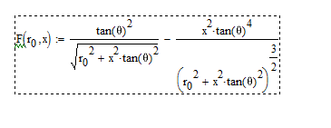
My mistake - I forgot about the square root. MathCad gives the 2nd derivative as shown below. The values at x=0 go lower, but the values above some point go higher.
d2/dx2 = (tan(b)^2*r_0^2)/(tan(b)^2*x^2+r_0^2)^(3/2)
That's right. So what is more advantageous from a HOM viewpoint?
That's a good question.
What I do know is that as the throat gets larger the HOMs cut-in frequencies get lower. Which has the higher values I don't know, but generally lower cut-in is not what one wants. In a 1" OS the first cut-in is at about 6 kHz. For a 2" it is about 3 kHz. I'd prefer the 6 kHz as that is nearly out of band.
BTW, what I add to the "pure" OS equation cited everywhere is a term that is taking the throat angle into account. It only shifts and scales the hyperbola accordingly (a little bit), so there is the desired angle for x=0. But it's still a "pure OS" contour, exactly, i.e. a hyperbola.
Last edited:
So do you think it would be possible to place such lens in front of an existing compression driver, shape the wavefront to spherical and use a conical waveguide?
There are several larger format drivers that have a phase plug ending at the very end of the driver, with zero exit angle. That might be an interesting exercise.
From spherical to flat required by your waveguide. Salt shaker type. Perfect task for photo resin printer.
That is not correct, it gets only shifted to the left - exactly what you want to do. No rotation. And of course the scale gets changed a little bit for the right throat radius. It is still an exact equation of a hyperbola, only the center is not in [0,0] but in [m, 0] - I can't remember the formula for m just now. I could show you the math...That term basically rotates the whole thing, which is not the same as starting the OS at a given angle. For an initial angle of 0, as you show, it's fine, but I would question its correctness for larger angles.
Last edited:
Mabat - I'll have to think about that.
As far as acoustic lense goes: I did my MS Thesis on them, made several. They don't work very well - at best - and they take a lot of space to do much. It's very hard to get a large enough index of refraction to make much curvature.
The way that I discovered the foam was along these same lines. Use the foam as a medium for refraction. The effect was very small on the polar response, but I found a significant audible effect that led me to investigate further.
Believe me, I have spent considerable amount of time on that.Mabat - I'll have to think about that.
This is the general equation of a hyperbola (two forms of the same). The point [m, n] is the center, etc. You can try to convert my OS formula to the first form - you'll see where the center is and what the semi-axes are.
Attachments
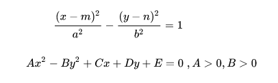

The most general equation of a conic section (any one of them) includes the x*y term:
Ax^2 + Bxy + Cy^2 + Dx + Ey + F = 0 (where at least one of A,B,C is not zero)
Then a rotation transform x,y -> x',y' (the sines and cosines) can be found that eliminates this term, but I've never looked into that much.
Ax^2 + Bxy + Cy^2 + Dx + Ey + F = 0 (where at least one of A,B,C is not zero)
Then a rotation transform x,y -> x',y' (the sines and cosines) can be found that eliminates this term, but I've never looked into that much.
Last edited:
I still wonder how to detect HOMs in these BEM simulations. Like the last question of the throat size, it would be interesting to see the influence. Is there any chance to trace higher order modes in this kind of numerical approach? I can imagine terminating the simulated waveguide with an absorptive boundary/cap so no mouth reflection or diffraction comes into play. Wouldn't the HOMs manifest as a non-spherical wavefront somewhere down the device?
I'd say that would be exactly correct. Any spherical shape can be expanded into modes and these is well know. So you just take the velocities on the surface of the sphere and find its modal representation. Those are the HOMs. The expansion must use spherical harmonics.
In case it's not clear, you would need to use a baffle and have the sphere some ways out from the mouth.
In case it's not clear, you would need to use a baffle and have the sphere some ways out from the mouth.
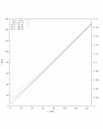
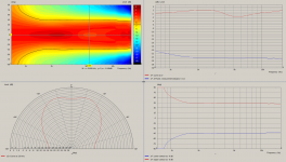
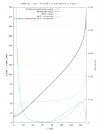
Some more simulation results, if anyone is interested. This time, the waveguides are a bit deeper with about the same mouth size as my last post (p. 28, #277). The overall result is as you might expect: directivity is held constant to a lower frequency, but there is more axial ripple. First is Marcel's superellipse-based equation with L=152.4; s=1; q=0.999; n=7.3. Next is a slope and curvature matched clothoid termination starting at 50% of the total depth. Last is a circular arc termination with a radius of 129mm (~5in). The clothoid termination looks the best to me in this case.
Attachments


- Home
- Loudspeakers
- Multi-Way
- Acoustic Horn Design – The Easy Way (Ath4)