No relatively even walls on your house?
Does not have to be very far field, most people listen between two and a half, to three and a half meters distance, no?
Just looking for what to expect, sans room modes.
Does not have to be very far field, most people listen between two and a half, to three and a half meters distance, no?
Just looking for what to expect, sans room modes.
sans room modes.
That's why a LARGE wall is needed. For example, assume you want to get rid of room modes (or other echo effects) in the SPL measurement down to 50 Hz. This is equivalent to an anechoic impulse response that is 200 ms long. Assuming a microphone distance of 1m from the driver, this requires that all objects (except the wall for half-space conditions) are at least 4m away from the driver. This means the speaker needs to sit in the middle of a wall that is at least 8m wide and 8m high. I don't have one of these in my workshop.
The only way out I see is what we did already (a while ago): use the nearfield response and transform this to the far field by (1) use of a baffle step calculator and (2) splice it to far field measurements at some higher frequency where anechoic measurements are available/possible.
Or am I in the wrong boat?
I was just thinking measurements, 2.5-3.5m distance, about listening height, middle of an outside wall with no obstructions either way.
No compensations or simulations. There is no perfect room, so this should be better than putting it in any room, but still give an impression of what to expect.
Or maybe I'm completely off my rocker.
Perhaps just measuring it in room, using a good spot you would like to place it when done.
No compensations or simulations. There is no perfect room, so this should be better than putting it in any room, but still give an impression of what to expect.
Or maybe I'm completely off my rocker.
Perhaps just measuring it in room, using a good spot you would like to place it when done.
Last edited:
The only way out I see is what we did already (a while ago): use the nearfield response and transform this to the far field by (1) use of a baffle step calculator and (2) splice it to far field measurements at some higher frequency where anechoic measurements are available/possible.
Or am I in the wrong boat?
I think that is the least compromised method. The only place error can creep in is below the splice, and it will result in a small shift of response up or down of +/- 1 dB if you take care. The error will be difficult to identify because it is so small. If you do smoothed in-room, or flex windowing, etc., you will have very noticeable ripples which you KNOW must be in error. So would you rather have a method that has errors so bad they are obvious, or so small it is difficult to identify? My .02 anyway
Just a quick update:
What do you guys think?
- I played a bit with the damping of the box. Doing what KaffiMann suggested a while back seems to work okay. Felt / "egg foam" on top of the divider of the bass reflex port, plus some foam on the sides of the woofer. I also added some foam on the top panel. I did not put any damping material in the way between the woofer and the bass reflex port. I have done some measurements (nearfield, acoustic) and a first quick look seems to show how the damping material reduces most of the internal resonances in the box (but I need to take a closer look at the data).
- The impedance curve and the nearfield measurements show a resonance at 250 Hz, which does not change much in response to the damping material in the box. The only way I found to reduce this resonance is to stuff the bass reflex port. 250 Hz corresponds to a wave length of 1.37m, which is pretty much 4x the length of the bass reflex port. Could this be some 1/4 wave resonance of some sort?
- Inspired by my earlier idea of trying a slightly shorter port I will try a BR100-HP bass reflex tube. I am not saying this will be "better" than the current port, but it will be easier to modify for testing purposes. Also, since it is shorter, it might provide some additional insight into the 1/4 wave resonance question above. A rough estimate shows that the BR100-HP should give a similar tuning as the current port. Then I can simply cut off little bits from the end of the tube to try different tuning options.
Question: where should I put the port? Rear or front (or even on the side or top panel)? I'd tend to put it on the back to reduce the effect of upper bass / lower midrange "leaking" out of the port. - I tried reducing the level of the tweeter a bit in the DSP filters (-1 dB). This improves the already good (perceived) sound balance even more; things just come together in a very good way. Implementing this change in the analog filter design will be easy.
What do you guys think?
Just a quick update:
...
- The impedance curve and the nearfield measurements show a resonance at 250 Hz, which does not change much in response to the damping material in the box. The only way I found to reduce this resonance is to stuff the bass reflex port. 250 Hz corresponds to a wave length of 1.37m, which is pretty much 4x the length of the bass reflex port. Could this be some 1/4 wave resonance of some sort?
...
What do you guys think?
I think the 250hz internal resonance is caused by the distance from driver to top, then reflection into port.
In grave danger of repeating myself infinitely, it is the sole reason I was not happy with the 12" drivers placement in the box, in relation to the port.
The only way to deal with it is to break it up, you cannot use that much dampening material in the box, it will NOT sound good.
The port is not the cause of this resonance, it is the drivers placement in relation to the internal walls that enable this resonance to occur, and at the same time allow it to enter the port almost directly. It is a problem that boosts itself. Break it up or live with it.
Edit:
And regarding the "tube port to exit back" thing, I do suggest you try it out. But please also try to listen to music like that, in a normal room.
My personal preference would be to keep the port "as-is", and break up the resonance inside the box.
Last edited:
I think the 250hz internal resonance is caused by the distance from driver to top, then reflection into port.
Hmm, I am not sure I get what you're saying, but I believe you're referring to a standing wave that develops between the bottom and the top of the enclosure. However, I am not sure that this really is the cause for the "250 Hz issue". The internal box height is 62cm, which would give a standing wave at about 280 Hz, not 250 Hz. Also, this standing wave would not be affected by stuffing the port (which it is!). I therefore don't think the "250 Hz issue" is due to a standing wave in the box.
In grave danger of repeating myself infinitely, it is the sole reason I was not happy with the 12" drivers placement in the box, in relation to the port.
...
The port is not the cause of this resonance, it is the drivers placement in relation to the internal walls that enable this resonance to occur, and at the same time allow it to enter the port almost directly. It is a problem that boosts itself. Break it up or live with it.
You suggested a while ago to break the internal standing wave with an angled divider in the box. I have tried that in the past (in a different project), and it didn't work. I guess the standing wave just goes around the divider.
I may have missed it, or maybe I can't remember it, but what exactly did you not like about the placement of the woofer and the port in relation to each other? What would be a better arrangement?
I try to put woofers and ports at golden ratios of the internal dimensions, or at 1/3rds. I avoid 1/4 and 1/2 at all costs. That said, this is one area I need to do more research on. How is your placement?
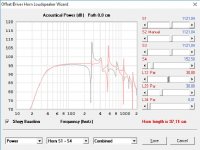
Here you go Matthias.
Actual driver placement in gray, ideal placement (red squiggly line) in this particular box, is smack in the middle.
Ideal placement pushes those nasty resonances to a frequency and amplitude they can be dealt with easily.
Edit:
If you can place a tube port of equal length and size, front and center, in this particular box, because the design is compromised for making certain compromises (Hah! a compromised compromise 😀), it might be better than the slot port.
Attachments
Last edited:
I try to put woofers and ports at golden ratios of the internal dimensions, or at 1/3rds. I avoid 1/4 and 1/2 at all costs. That said, this is one area I need to do more research on. How is your placement?
See drawing attached in post 346.
What is the concept / idea behind placing the woofer and the port at golden ratios or 1/3rds of the internal dimensions?
Here you go Matthias.
Actual driver placement in gray, ideal placement (red squiggly line) in this particular box, is smack in the middle.
Ideal placement pushes those nasty resonances to a frequency and amplitude they can be dealt with easily.
I do not understand how that model works. Since the box dimensions are the same for both curves, the resonances due to standing waves that develop between the walls of the box should be the same. This is clearly not what the model does. So what's the process/mechanism in this model that is responsible for the different results at different placements of the woofer in the box?
Assuming there is a way to make sense of the underlying processes that result in the different model outputs, the following would be interesting:
- Can you run that model with a "stuffed port" (i.e., no port at all)? It would be interesting what the model does with those resonances, and how it compares to what I am observing in the real world.
- In a next step, it would be interesting to see what the model does with the woofer placement as it is in the Monkey Coffin (since we cannot change that a lot), but with the port at different positions. Where is the best position for the port?
If you can place a tube port of equal length and size, front and center, in this particular box
Now this is beyond me. Can you explain? What is the meaning of "equal length and size, front and center"? What's the idea here?
...
I do not understand how that model works. Since the box dimensions are the same for both curves, the resonances due to standing waves that develop between the walls of the box should be the same. This is clearly not what the model does. So what's the process/mechanism in this model that is responsible for the different results at different placements of the woofer in the box?
Again, at the risk of repeating myself ad nauseum, it is the placement of driver in relation to internal walls, bottom and top. It is the sole reason I prefer simulating BR boxes in Hornresp, and also why I use the horn segments and not the BR function for simulation. I want to see what issues might surface, smooth curves on simulations makes me think that not everything is accounted for.
Assuming there is a way to make sense of the underlying processes that result in the different model outputs, the following would be interesting:
- Can you run that model with a "stuffed port" (i.e., no port at all)? It would be interesting what the model does with those resonances, and how it compares to what I am observing in the real world.
- In a next step, it would be interesting to see what the model does with the woofer placement as it is in the Monkey Coffin (since we cannot change that a lot), but with the port at different positions. Where is the best position for the port?
No port = nowhere the resonances can escape. A closed box would also have more stuffing, so any internal reflections would not cause resonances to the same degree.
There are some limits on where I can simulate port placement.
But following logic and reflections, a tubed port would be better in the middle, since that is the optimal driver placement.
And a slot port would be much better at the opposite side from the 12", IE the top of the enclosure. But you and Paul had some strong objections against this, mainly because of issues with diffraction.
Now this is beyond me. Can you explain? What is the meaning of "equal length and size, front and center"? What's the idea here?
The port should not be any smaller, it might cause problems with turbulence at certain frequencies/volumes. To retain the same tuning, a port with equal cross sectional area, should also be of the same length. I do suspect you might end up with a slightly higher measured tuning anyway, since the tube port will have slightly less drag resistance/allows higher air speed in the center.
KaffiMann, I believe I am missing some crucial piece of context. I can't make sense of your model curves, and I feel pretty stupid about this. I'd like to understand what's going on behind the scenes of your model runs, and how to interpret the model curves. I am trying to understand the processes that lead to the curves you have shown. So here I go again...
Well, yes, I understand that. But why does the driver placement make a difference in the model? What is the process behind this?
Uhm, what about the driver? If the air inside the box resonates, the driver cone will go with it.
Sure. But I am just trying to make sense of what the model does, and how it does it. That's why I asked for the "no port" model run.
Let's assume for a moment that I'd understand why+how driver placement would make a difference. The next question would then be: why would the optimal port placement where the optimal driver placement is? What is the logic behind this?
Why would the optimum placement of a slot port be different than for a round tube?
Yes, placing the port on the front panel next to the mid+tweeter might not be great considering diffraction. But what about the port on the back of the enclosure. Anything wrong with that?
I am aware of this. My idea was to compare the tuning(s) between the current slot port and the round tube by measurement (impedance, nearfield SPL, cone excursion).
Again, at the risk of repeating myself ad nauseum, it is the placement of driver in relation to internal walls, bottom and top.
Well, yes, I understand that. But why does the driver placement make a difference in the model? What is the process behind this?
No port = nowhere the resonances can escape.
Uhm, what about the driver? If the air inside the box resonates, the driver cone will go with it.
A closed box would also have more stuffing, so any internal reflections would not cause resonances to the same degree.
Sure. But I am just trying to make sense of what the model does, and how it does it. That's why I asked for the "no port" model run.
There are some limits on where I can simulate port placement.
But following logic and reflections, a tubed port would be better in the middle, since that is the optimal driver placement.
Let's assume for a moment that I'd understand why+how driver placement would make a difference. The next question would then be: why would the optimal port placement where the optimal driver placement is? What is the logic behind this?
And a slot port would be much better at the opposite side from the 12", IE the top of the enclosure.
Why would the optimum placement of a slot port be different than for a round tube?
But you and Paul had some strong objections against this, mainly because of issues with diffraction.
Yes, placing the port on the front panel next to the mid+tweeter might not be great considering diffraction. But what about the port on the back of the enclosure. Anything wrong with that?
I do suspect you might end up with a slightly higher measured tuning anyway, since the tube port will have slightly less drag resistance/allows higher air speed in the center.
I am aware of this. My idea was to compare the tuning(s) between the current slot port and the round tube by measurement (impedance, nearfield SPL, cone excursion).
...I'd like to understand what's going on behind the scenes of your model runs, and how to interpret the model curves...
Well blank myself about acoustics inner of ported system and also running Hornresp, that said think if we did spend few minutes on below page should get us more or less going about using Hornresp and ported system understanding.
The Subwoofer DIY Page - Ported Systems
I see. Well, to be honest, I do not have the full understanding myself, you would have to ask David about this.KaffiMann, I believe I am missing some crucial piece of context. I can't make sense of your model curves, and I feel pretty stupid about this. I'd like to understand what's going on behind the scenes of your model runs, and how to interpret the model curves. I am trying to understand the processes that lead to the curves you have shown. So here I go again...
But after spending some years doing a few hours of simulations every single day, I've come to see patterns that say something about the distances inside the box. I am no good at maths, and horrible at theory, but I do have a fairly good spatial understanding, and can easily manipulate shapes, signals and reflections in my head.
It coincides with measured results, it is caused by certain frequencies bouncing around between the internal surfaces. Ask David about the math behind it.Well, yes, I understand that. But why does the driver placement make a difference in the model? What is the process behind this?
You are correct, but the increase in damping material will largely negate the effect. (and it does not show up in the simulation quite the same way, the effect may be overly reduced by the "closed box" simulation).Uhm, what about the driver? If the air inside the box resonates, the driver cone will go with it.
It does not come up the same way in closed box simulations, I aim for getting realistic simulations, not pretty simulations.Sure. But I am just trying to make sense of what the model does, and how it does it. That's why I asked for the "no port" model run.
This only counts for the tube port, because that is a point in the box where the 250hz does not resonate.Let's assume for a moment that I'd understand why+how driver placement would make a difference. The next question would then be: why would the optimal port placement where the optimal driver placement is? What is the logic behind this?
Because it is very unpractical to place a slot port in the middle of the enclosure. Better to use an existing boundary.Why would the optimum placement of a slot port be different than for a round tube?
You're welcome to try, I do not like it because I find it can boost some room mode issues much more than a front port. And I find a front port gives more "impact" (not more sound) even at low volumes, this is why I also like to have the port higher up from the floor, the measured sound is not directional, but the initial pressure change is. It is a bit like hearing a reflection vs hearing the same sound unreflected, only very low in frequency.Yes, placing the port on the front panel next to the mid+tweeter might not be great considering diffraction. But what about the port on the back of the enclosure. Anything wrong with that?
If you like having the port on the back and have no room issues, please continue to enjoy the rear port.
I will look forward to seeing your results.I am aware of this. My idea was to compare the tuning(s) between the current slot port and the round tube by measurement (impedance, nearfield SPL, cone excursion).
...think if we did spend few minutes on below page should get us more or less going about using Hornresp and ported system understanding.
The Subwoofer DIY Page - Ported Systems
I had a quick look at the link, and it does explain the internal resonances. As far as I can tell, it's just good old standing waves that develop between the (parallel) panels of the box. As he changes the "Lrc" parameter (the depth of the box) to 0.4m, a standing wave develops at 2 x Lrc = 0.8m, which shows up at 343m/s / 0.8m = 428 Hz (simple Kindergarden math). Note that this result does not depend on the position of the driver in the box. KaffiMann suggested something else, so I guess there must be something in Hornresp that I am missing (and I refuse to believe the Hornresp curves as long as I don't understand them 😀).
I see. Well, to be honest, I do not have the full understanding myself, you would have to ask David about this.
Who is David? Can you please ask him?
...This only counts for the tube port, because that is a point in the box where the 250hz does not resonate.
Naaaah. It is not possible for an internal resonance (standing wave) to occur only at some spots in the enclosure, but not at others. Either it's everywhere, or it does not exist. After all, a standing wave works by filling the whole box!
You're welcome to try, I do not like it because I find it can boost some room mode issues much more than a front port.
Why would that be the case? For a tuning frequency of 50 Hz, the wavelength is 6.9m (and longer for lower tuning frequencies), and the sound irradiation in spherical. Moving the port from the front to the back of the enclosure would move the "center of the sphere" back by about 40 cm, which is less than 6% of the wavelength. I would have thought that's pretty much irrelevant.
I can see only one situation where a rear port would be a problem. If the speaker would be positioned very close to a wall or cramped into a bookshelf, a rear port would be blocked by the wall (and the books).
I find a front port gives more "impact" (not more sound) even at low volumes, this is why I also like to have the port higher up from the floor, the measured sound is not directional, but the initial pressure change is.
Well, the "initial pressure change" is only directional if it's frequency is higher than the baffle step, which means well above 100 Hz. I'd prefer if the port would keep this lower midrange sound inside the box instead of acting as a leak that allows lower midrange sound to escape from the inside of the enclosure. Stopping this leakage would require stuffing some damping material into the port. This would also reduce the low frequency bass from the port, which we don't want. The only way to deal with this I can see is to send the "leaking midrange" backwards, away from the listener. The directionality would help to keep this "leakage" away from the listener a bit -- but I don't know how well this idea really works out.
I will look forward to seeing your results.
Me too... I am pretty sure I will learn a few things, possibly the hard way. 🙄
Last edited:
I had a quick look at the link, and it does explain the internal resonances. As far as I can tell, it's just good old standing waves that develop between the (parallel) panels of the box. As he changes the "Lrc" parameter (the depth of the box) to 0.4m, a standing wave develops at 2 x Lrc = 0.8m, which shows up at 343m/s / 0.8m = 428 Hz (simple Kindergarden math). Note that this result does not depend on the position of the driver in the box. KaffiMann suggested something else, so I guess there must be something in Hornresp that I am missing (and I refuse to believe the Hornresp curves as long as I don't understand them 😀). ...
I am really not suggesting anything else, you got it wrong.
I just do not know how to explain it to you, so you can understand.
There is no magic involved.
What is resonance, and why do parallel surfaces trigger them?
Very, very short explanation:
If a driver has short distance to boundaries it will trigger resonant behaviour in higher frequencies.
If a driver has longer distance to boundaries it will trigger resonant behaviour in lower frequencies.
Higher frequencies are easier to damp down because they have a shorter wavelength, therefore resonant behaviour pushed up higher will be easier to isolate.
Lower frequencies are harder to damp down because the wavelengths are longer, and resonant behaviour in low frequencies require much more material to deal with.
I like you Matthias, but you show some very flawed logic.
By your line or reasoning there should be no difference in sound pressure level througout a room. And all resonances should come through at an equal volume and pressure no matter what surfaces they trigger from.
This is false.
You can easily hear the phase disturbance by reflection of a boundary, it is not double or half signal strength, it is disturbance in phase from reflections that come in adittion to the original signal. And these reflections cause a "perceived" boost or loss, pending on where in the room the signals meet.
It is the exact same thing that happens inside a speaker box, only on a much smaller scale.
You can hear the phase variations in room modes yourself, extremely easy to do, you just have to really understand that it is not a boost in signal strength, it is a reflection of the signal, skewed in phase in relation to the original.
Software tools can only simulate so much. I used to run a lot of akabak sims, but after a while I came to see that Hornresp was much easier to use, and eventually came incredibly close to the akabak results, so seeing as akabak is no longer in development, and requires an XP machine, I came to rely more on Hornresp.
David Mcbean is the creator of hornresp, he has a sticky thread in the subwoofer forum.
Do not trust Hornresp? Not a problem for me, but then by your definition that 250hz resonance should not exist.
I like you Matthias, but you show some very flawed logic.
Ok, I will try to improve on the "but" part then 🙂
I am really not suggesting anything else, you got it wrong.
You suggested the resonance depends on the placement of the woofer in the box. My explanations showed that the resonances shown in BYRTTs link just depend on the internal dimension(s) of the box, and they are not related to the placement of the woofer. This simply means we are not referring to the same processes. It does not mean that I got it wrong.
[...regarding room modes...] By your line or reasoning there should be no difference in sound pressure level througout a room ... This is false.
This would be very wrong indeed! However, that's not what I was referring to. I believe this shows the root of where our misunderstanding(s) come from.
Here's what I wrote: "It is not possible for an internal resonance (standing wave) to occur only at some spots in the enclosure, but not at others. Either it's everywhere, or it does not exist. After all, a standing wave works by filling the whole box!" Note that I did not write anything about sound pressure. I was just referring the to wave as a whole, which is characterised by sound pressure and acoustic particle velocity.
Now, for a standing wave between two parallel walls (of a room or a loudspeaker enclosure), the particle velocity is zero at the walls (nodes), because the walls block any movement. For the first mode, the particle velocity is largest in the center between the walls. For higher modes, there are nodes in between the walls where the particle velocity is zero. At the same time, the sound pressure is at its maximum at the nodes. You are therefore right that sound pressure is not spatially uniform for standing waves, but the wave as a whole (pressure+velocity) still exists everywhere!
Now that I believe to understand your "pressure-centric" view at standing waves I wonder if you're saying that the bass reflex port or the driver should be placed where the nodes of the standing waves occur (or possibly also the other way round: away from the nodes)? Is this it? If so: what would be the explanation for it?
Software tools can only simulate so much ... Do not trust Hornresp?
It's not that I don't trust Hornresp. It's just that I don't understand the processes that are included in the model, so I find it difficult to interpret the results. As long as I don't know what processes are in the model I cannot interpret the results such that I can use them to tweak a real-world loudspeaker system.
...but then by your definition that 250hz resonance should not exist.
My logic is the other way round. I know the 250 Hz resonance exists, because that's what the measurements tell me. I'd like to do something against this resonance, so I need to understand the process that causes it. A computer tool that works on a model with processes that are unknown to me will therefore not help me.
The only thing I understand so far is that the 250 Hz effect is not easy to explain with a standing wave within the enclosure because (a) the effect goes away if the port is stuffed (which has nothing to do with internal standing waves) and (b) the box dimensions don't match the 250 Hz frequency.
You suggested the resonance depends on the placement of the woofer in the box. My explanations showed that the resonances shown in BYRTTs link just depend on the internal dimension(s) of the box, and they are not related to the placement of the woofer. This simply means we are not referring to the same processes. It does not mean that I got it wrong.
Yes, it does change. What can a loudspeaker enclosure be compared to? Hmmm. Lets see if there's anything around us that is comparable, oh! maybe, I dunno, a room?
Does the sonic characteristic, the resonant frequencies, the nulls and the peaks, change, pending on where in the room you place a loudspeaker?
What happens inside a loudspeaker enclosure is directly comparable to what happens to sound waves in a room. A loudspeaker = a small room inside another room/space.
The walls do not primarily block movement, it is reflected. More below."It is not possible for an internal resonance (standing wave) to occur only at some spots in the enclosure, but not at others. Either it's everywhere, or it does not exist. After all, a standing wave works by filling the whole box!" Note that I did not write anything about sound pressure. I was just referring the to wave as a whole, which is characterised by sound pressure and acoustic particle velocity.
Now, for a standing wave between two parallel walls (of a room or a loudspeaker enclosure), the particle velocity is zero at the walls (nodes), because the walls block any movement. ...
If there's any way to understand my view, it would be best described as "wave centric".Now that I believe to understand your "pressure-centric" view ...
I imagine the frequencies emitted from the drivers as waves, the waves come from a disturbance in the space, spread out throughout the enclosure, reflect off surfaces, collide with each other, some times null each other out because that is what happens when two waves of inverted phase meet. Some times you get small waves on top of bigger waves, some times the phase difference will make waves seem stronger when they are merely disturbed.
Waves are not equal throughout a volume, put your finger in a box/container with water, you create waves, the waves are reflected off the surrounding surfaces, pending on where you create the waves you will change where the waves are reflected, where they cancel each other, where they add to each other. If you use a round container you get a completely different result from if you use something like the square deep pan from the oven. It is the same inside a room, or inside a loudspeaker.
I've had some of this discussion before, with Silverprout, will try and find the thread.
In my limited experience, the "wave centric" view holds up very well.
Please remember that I am entitled to some insanity.
The 250hz resonance can be dampened in the port, because that is where it escapes.
You can for instance imagine lines from the speaker cone, one goes up, reflects off the top, enters the port. It could also go other ways. How long is it from the speaker cone, to the top, then to the bottom of the port?
You will have to accept any typos, I got to watch the kids use hammers and nails.
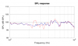
The postman delivered the round bass reflex ports (Monacor BR-100HP) I ordered for testing. I installed one in the Monkey Coffin (centered on the rear panel) and measured the nearfield SPL response of the woofer:
You can clearly see that funny things happen at 250 Hz with the front/slot port open (red curve). No such resonance happens with the rear/round port, which is quite a bit shorter than the front/slot port. This indicates that the 250 Hz issue happens within the long slot port, not in the enclosure.
I'll continue by taking a closer look at the bass reflex tuning with the new port, and also do some listening tests.
- Red curve: front/slot port open, rear/round port closed (filled with compressed foam)
- Blue curve: Rear/round port open, front/slot port closed (filled with compressed foam)
- Black curve: Both ports closed (filled with compressed foam)
You can clearly see that funny things happen at 250 Hz with the front/slot port open (red curve). No such resonance happens with the rear/round port, which is quite a bit shorter than the front/slot port. This indicates that the 250 Hz issue happens within the long slot port, not in the enclosure.
I'll continue by taking a closer look at the bass reflex tuning with the new port, and also do some listening tests.
Attachments
- Home
- Loudspeakers
- Multi-Way
- Open Source Monkey Box