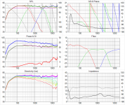
I can see how the group delay would be different for the individual driver responses, I don't see this for the complete system. In fact, the group delay curves (top right panel) look rather similar to me for all three simulations.
...
I feel stupid... Was looking at the wrong graph, impedance plot... *Duh*
Feel free to rub it in.
I feel stupid... Was looking at the wrong graph, impedance plot... *Duh*
Feel free to rub it in.
Well, I'd say that the labelling of the Vituix graphs isn't exactly great. There are no axis labels, no units, and 1 kHz seems to be the same as 10 kHz. 😀
About the capacitance, a 33 μF and 82 μF cap in series seems to be about 23.5 μF?
I seem to remember it's the opposite of resistors, so in series it's lower, in parallel it's higher.
I seem to remember it's the opposite of resistors, so in series it's lower, in parallel it's higher.
About the capacitance, a 33 μF and 82 μF cap in series seems to be about 23.5 μF?
I seem to remember it's the opposite of resistors, so in series it's lower, in parallel it's higher.
Yes -- but if there's something else connected where the two caps meet, you can't combine the two caps into one because you'd loose that connection point.
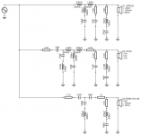
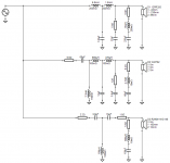
Here are some revisions of my filter simulations in post 664.
The rules that I "applied" during the tweaking were about the same as before (smooth+flat overall system SPL response, good off-axis and power response, no funny peaks/dips in the electronic filter curves). In addition I made sure the acoustic filter slopes were approximately symmetric around the x-over points, and I tried to make the filter curves a bit smoother than for instance the EL3 filter in post 664.
First, I improved the "conventional" filter (option (3) in post 664) to give an overall flatter response. While I was at it, I added a resistor before the filter(s). Splitting the attenuation resistances between before/after the filter(s) helps tweaking the filter transfer curves. This also helped to reduce the "directivity blip" at 2.5 kHz. Let's call this filter version the "Conventional 3B".
Then I went back to the elliptic filters (options (1) and (2) in post 664) to see if they can also be improved using the "split resistances". I played around with many options, and in the end I found a nice solution with the EL3. This involved making the second series capacitor in the midrange filter so large that it became ineffective, so I simply deleted it. The midrange filter circuit was now the same as in the EL4 filter (but with different part values). I tried adding the parallel capacitor in the woofer filter as in the EL4 filter, but couldn't tweak the system to a better response, so I removed that capacitor again (leaving the EL4/option-2 from post 664 in the dust). The resulting circuit is a mix between Pauls EL3 and EL4 proposals (but with different part values and different filter transfer curves). The voltage transfer curves are quite a bit smoother than before, and I really like the overall simulation results. Let's call this version the "Elliptic 3.4mix".
Simulation results and x-over schematics are attached. Comments, suggestions?
Attachments

1st of all, here's the Open Source meaning: "Open source is a term denoting that a product includes permission to use its source code, design documents, or content."
This means that a license is required to define a product as open source.
I don't see any mention of the word "license" in that Wikipedia sentence. I don't follow your logic. I am pretty sure I can call anything the way I want, as long as that name is not registered/protected by law. For instance I could call my cat "Open Source" without giving it a license (although my family would think I am going nuts again). Don't get me wrong, I am not against licenses. I am just not convinced we need one here.
...Comments, suggestions?
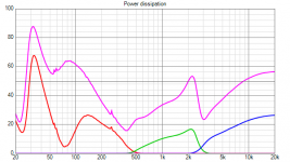
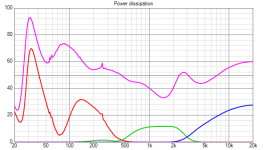
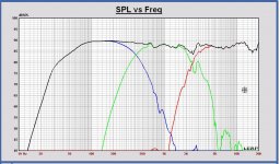
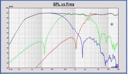
Nice work there 🙂 maybe no problem then ignore this post but WM752 opens up in lows now and don't know where its wattage comfort zone is, for example 20 volt input show 1 watt at 190Hz for option two post 685 where option one post 664 show 1 watt up higher at 450Hz.
First graph below is option one post 664 and second graph is option two post 685.
Attachments
Nice work there 🙂 maybe no problem then ignore this post but WM752 opens up in lows now and don't know where its wattage comfort zone is, for example 20 volt input show 1 watt at 190Hz for option two post 685 where option one post 664 show 1 watt up higher at 450Hz.
First graph below is option one post 664 and second graph is option two post 685.
That's a good catch (although I am not sure which curve to look at, but I guess you're referring to the green curve). I am not worried about the power at all. 1 Watt is a piece of cake for this driver.
However, cone (dome) excursion could be more interesting. If the voice coil leaves the linear range of the motor due to low frequency "leakage", distortion will go up. Since I couldn't quickly find a way to calculate cone excursion, I simply measured it (peak-to-zero at 200 Hz): 0.36 mm with 6.1 Vrms at driver terminals and 0.62 mm with 9.9 Vrms at driver terminals. 1 Watt into 10 Ohm (impedance at 200 Hz) is about 3.3 Vrms, so cone excursion would be about 0.2 mm. Volt give Xmax = ±1 mm in their TSP specs. So even at 20 Vrms input to the filter (1 Watt or 3.3 Vrms into the driver), cone excursion would remain at 20% of the specified max. Should be fine.
--- Since I couldn't quickly find a way to calculate cone excursion, I simply measured it (peak-to-zero at 200 Hz): 0.36 mm with 6.1 Vrms at driver terminals and 0.62 mm with 9.9 Vrms at driver terminals. ---
Interesting! But how did you measure that by 1/100 of millimeters, laser scanning?
Interesting! But how did you measure that by 1/100 of millimeters, laser scanning?
The last digit is always the "uncertainty digit", so I wouldn't say that I measured this to 1/100 millimeter.
I simply put a flat piece of aluminium across the driver and then used a (digital) caliper to measure the distance to the dome while no signal was playing, and zeroed the caliper there. Then I turned on the test signal and measured again. It's actually easier than you might think.
Matthias, that looks very nice!
Have you tried listening to the filters yet?
I think we are close enough that you get to decide the winner by ear, are you up for it?
Have you tried listening to the filters yet?
I think we are close enough that you get to decide the winner by ear, are you up for it?
Matthias, that looks very nice!
Have you tried listening to the filters yet?
Not yet. I will need the services of our biquad coefficient magician for that. But I wanted to see if there are any obvious issues with those designs before doing the biquad work.
I think we are close enough that you get to decide the winner by ear, are you up for it?
Yup, that was my idea also! However, we should not forget that these are simulations only. From experience, the real world tends to come up with some surprises here and there.
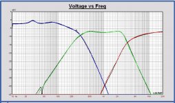
Since there are no more complaints about those filter designs, here are the filter transfer curves (voltage at driver terminals) for the "Conventional 3B" and the "EL34mixed" versions.
Paul, can you convert these to miniDSP biquad coefficients so that I can test them in the prototype?
Paul, can you convert these to miniDSP biquad coefficients so that I can test them in the prototype?
Attachments
Sorry for this collateral "confrontation", but I believe that nowdays is VERY important.
From opensource.guide:
And even if you choose the "no copyright" way, it needs - it's not a paradox - a declaration (aka license) too:
Last but not least, you can - of course - choose the "no licensing" path, but (to me) is counterproductive.
It's not "my" logic, it's how open source works.I don't see any mention of the word "license" in that Wikipedia sentence. I don't follow your logic.
From opensource.guide:
Starting an Open Source Project said:No matter which stage you decide to open source your project, every project should include the following documentation:
As a maintainer, these components will help you communicate expectations, manage contributions, and protect everyone’s legal rights (including your own).
- Open source license
- README
- Contributing guidelines
- Code of conduct
[..]
An open source license guarantees that others can use, copy, modify, and contribute back to your project without repercussions. It also protects you from sticky legal situations. You must include a license when you launch an open source project.
Of course you can call your cat as you want (even "Trump", for example), but the "Open Source" term usage needs to respect OSI guidelines:I am pretty sure I can call anything the way I want, as long as that name is not registered/protected by law. For instance I could call my cat "Open Source" without giving it a license (although my family would think I am going nuts again).
...and this also applies to hardware projects, since "Open Source" is a registered trademark.OSI Trademark Guidelines said:the use of the term "Open Source" is used solely in reference to software distributed under OSI Approved Licenses.
On contrary I'm an open source fan/promoter, so I "trust" licenses...Don't get me wrong, I am not against licenses. I am just not convinced we need one here.
And even if you choose the "no copyright" way, it needs - it's not a paradox - a declaration (aka license) too:
- Creative Commons Attribution 4.0 International (CC BY 4.0)
- CC0 - “No Rights Reserved”
- Public Domain Mark - "No Known Copyright"
Last but not least, you can - of course - choose the "no licensing" path, but (to me) is counterproductive.
Last edited:
Matthias, I will do. For the EL34mix the woofer file is corrupt, no realistic values. Can you have a look at it?
Matthias, I will do. For the EL34mix the woofer file is corrupt, no realistic values. Can you have a look at it?
Here's the correct file.
Attachments
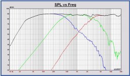
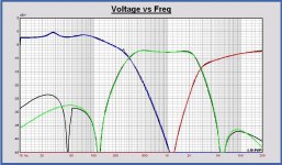
Here the biquad version for miniDSP of the 2 Matthias' designs. The transfer level decreased 1.5 dB to avoid digital overflow.
In attach also the voltage transfers of both xo (targets in grey) and the SPL of the digital filtered drivers as a check.
I have not looked in detail to the design itself. Difficult to interprete it with the the Vituix plots. Without any targets to compare the design with. In this way we can make thousands of options that might sound as ok.
IMO it is best to make a design as close as possible to a reference with known performance. With some tuning around it for the best compromise of all the system parameters and comparing always with the reference.
By deviating far from reference targets, 'something' will be realized and it is difficult to interprete it on all the behavior parameters. In a way one is not sure anymore the drivers are acting in the same way. For example a woofer and midrange both acoustically filtered B3 will have the same timing behavior, just because they are both close to the same B3 polynomial. That is not the case anymore deviating more and more from that target.
Attachments
-
 V67 Monkey Box D Conventional 3B xo transfers.JPG145 KB · Views: 290
 -
 V67 Monkey Box D Conventional 3B SPL with digital filter.JPG184.2 KB · Views: 283
 -
 V67 Monkey Box D Conventional 3B SPL with digital filter 10dB-div.JPG184.3 KB · Views: 281
 -
 V68 Monkey Box D EL34mix xo transfers.JPG143.6 KB · Views: 279
 -
 V68 Monkey Box D EL34mix SPL with digital filter.JPG181.6 KB · Views: 273
 -
 V68 Monkey Box D EL34mix SPL with digital filter 10dB-div.JPG187.7 KB · Views: 113
 -
V67 MonkeyBox Dig Conventional3B biquad coeffs.zip1.6 KB · Views: 76
-
V68 MonkeyBox Dig EL34mix biquad coeffs.zip1.6 KB · Views: 77
Last edited:
Here the biquad version for miniDSP of the 2 Matthias' designs.
Thank you Paul! The biquads seem to be very close copies of the Vituix output!
I have not looked in detail to the design itself. Difficult to interprete it with the the Vituix plots. Without any targets to compare the design with. ...
In a way one is not sure anymore the drivers are acting in the same way. For example a woofer and midrange both acoustically filtered B3 will have the same timing behavior, just because they are both close to the same B3 polynomial. That is not the case anymore deviating more and more from that target.
I agree that it is hard to say if my filter designs still follow some (textbook) target curves (maybe they don't). However, I have tried to get symmetric slopes (acoustic) at the x-over points in order to get consistent phase. Also, the Vituix simulation takes into account the phase/timing of the driver outputs, and the simulations do show good response of the summed output at the x-over points.
I will load the biquads to the miniDSP and will then come back with the results.
Hi Paul
Just to check: can you show a comparison of the phase curves of the biquads and the Vituix simulation?
Just to check: can you show a comparison of the phase curves of the biquads and the Vituix simulation?
- Home
- Loudspeakers
- Multi-Way
- Open Source Monkey Box