Since there is a minidsp available and set up, you can quite easily test different xo topologies and save 4 configurations on the board. Then it is easy to change config and listen to them.
Small wiggles in response, be it from a driver or xo don't necessarily sound bad at all. It depends very much on how it behaves off-axis. It might take several days and different kind of music to find the best config for a specific multi-way speaker. 2-ways are piece of cake compared to 3-way, especially when midrange has narrow passband.
Small wiggles in response, be it from a driver or xo don't necessarily sound bad at all. It depends very much on how it behaves off-axis. It might take several days and different kind of music to find the best config for a specific multi-way speaker. 2-ways are piece of cake compared to 3-way, especially when midrange has narrow passband.
Haven't tried mixed order filters yet. It was what saved me when I had my big 4 way setup some years ago.
Edit:
Very certain I've posted this earlier in the thread, but it was a big help to me in understanding some of the important basics of filters.
A Bessel Filter Crossover, and Its Relation to Others
Edit2:
Just one specific example:
It is a very good read, a "must" for everyone IMO.
Edit:
Very certain I've posted this earlier in the thread, but it was a big help to me in understanding some of the important basics of filters.
A Bessel Filter Crossover, and Its Relation to Others
Edit2:
Just one specific example:
Rane's Bessel Crossover at -3 dB
Rane's Bessel crossover in Halogen is set for phase match between low-pass and high-pass. This minimizes lobing due to driver separation, and also results in a pretty flat combined response. Another popular option is to have the magnitude response -3 dB at the design frequency. If -3 dB is desired at the setting, the frequency settings need to be changed by particular factors.
You will need to enter separate values for low-pass and high-pass: multiply the low-pass and high-pass frequencies...
For example, for a second-order low-pass and high-pass set to 1000 Hz, set the low-pass to 1272 Hz and the high-pass to 786 Hz.
It is a very good read, a "must" for everyone IMO.
Last edited:
These EL3 targets are a compromise between ripple and the width of the overlap band between the drivers. It is possible to make the sum response flat, but with a wider driver overlap. In my targets I choosed for the smallest overlap and the lowest ripple. Different elliptical configurations are possibe, but I didn't tried them out yet.Can't stop thinking it has been there all the time simulation or not including if one use optimal textbook smooth responses and is inherent non ideal compromise to filter type even if we had not any AC timing plus spacing mismatch, some plot scales mask the fenomen but its there in all of them below.
Hello Paul,
Why not keep the EL3 Lowpass for the woofer, but ad an LCR suck-out to deal with the 1-5kHz "mountain". In LEAP, that would be a breeze .
Why not keep the EL3 Lowpass for the woofer, but ad an LCR suck-out to deal with the 1-5kHz "mountain". In LEAP, that would be a breeze .
I am accustomed to LR symmetrical filters, I have tried duelund, first order, Bessel etc. and S.Harsch with minidsp and Hypex, but I just don't get them working and sounding right. Steep filters like LR48 are more forgiving to make response look right, but sound is eery instead of airy like with poor timing.
... I see. What about 4th order BW for woof/mid?
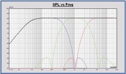
...with the tweaked woofer filter the outband reduction between 1 and 2 kHz is 5 dB worse than the original targets.
In the plot the SPL of the modified filter and the original targets.
I did see it while making the digital version of the tweaked filter, but I thought it was your idea to do the modification like that.
Maybe it is better to reduce the woofer outband conform the targets.
Can't stop thinking it has been there all the time simulation or not...
Haven't tried mixed order filters yet.
Why not keep the EL3 Lowpass for the woofer, but ad an LCR suck-out to deal with the 1-5kHz "mountain". In LEAP, that would be a breeze .
All in all, we seem to agree that we need to revise the current x-over design in some way. I did see the leakage of the woofer filter in the simulation, but didn't think it would actually be noticable in the summed response. Since no one complained about it, I just didn't care (let alone check it in the simulation...). Lesson learned!
I'd suggest to try the following in order to proceed from here:
- Keep the current filter concept, but reduce the leakage of the EL3 woofer low pass.
- Change the woofer/midrange x-over to something similar to a Bessel or Butterworth type with monotonic slopes. The slopes wouldn't be as steep at the elliptic ones, though.
- Change the entire x-over to Bessel or Butterworth type filters.
I will try option (1) in my Vituix simulation, but it would be good if someone else would also have a look at this, too.
Would option (2) (mixed filter types) be very wrong? Technical issues? Sacrilege?
Also, other options and ideas are welcome!
I would go for option 2, the mid has a sharper roll off, and does not need to change from 3rd order elliptic, but the woofer should maybe change to 4th order BW.
Offsetting xo points should be mandatory IMO, take into account the drivers response, textbook filters are for textbook examples, IE: perfect response imaginary drivers.
With software you can just schew the targeted xo point until the response changes to your liking.
Offsetting xo points should be mandatory IMO, take into account the drivers response, textbook filters are for textbook examples, IE: perfect response imaginary drivers.
With software you can just schew the targeted xo point until the response changes to your liking.
Hello Paul,
Why not keep the EL3 Lowpass for the woofer, but ad an LCR suck-out to deal with the 1-5kHz "mountain". In LEAP, that would be a breeze .
Hi Eelco
That is an option yes, but it will make the passive filter version more complex. Then also a fifth order elliptical version can be considered with -55 dB outband reduction, but it all means many components.
It is also possible to improve the sum response flatness, with a wider overlap between the drivers, I will have a look at it...
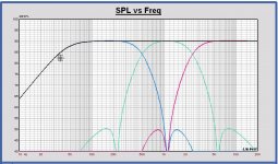
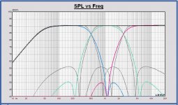
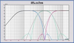
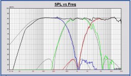
And what about an EL4? Targets in first plot for a xo at 500 and 2500Hz. Compared with EL3 and LR4 at same xo points in other plots.
You can see the EL3, I designed before, is more brickwall around the xo points. EL4 has a more LR4 behavior.
Anyway I will test the EL4 on my own speaker with miniDSP, how it sounds. First time I will design such one.
EL4 450 - 2500 Hz is also possible of course...
You can see the EL3, I designed before, is more brickwall around the xo points. EL4 has a more LR4 behavior.
Anyway I will test the EL4 on my own speaker with miniDSP, how it sounds. First time I will design such one.
EL4 450 - 2500 Hz is also possible of course...
Attachments
Preparation of response measurements for crossover simulation with VituixCAD
https://kimmosaunisto.net/Software/VituixCAD/VituixCAD%20Measurement%20Preparations.pdf
https://kimmosaunisto.net/Software/VituixCAD/VituixCAD%20Measurement%20Preparations.pdf
Preparation of response measurements for crossover simulation with VituixCAD
https://kimmosaunisto.net/Software/VituixCAD/VituixCAD%20Measurement%20Preparations.pdf
The question is not how to get data for x-over simulation it in Vituix (or any other software package). The question is which way to go in terms of x-over concept (type of filters, complexity vs. simplicity, etc.).
In my opinion, the circuit of the current EL3 concept reflects about the limit of parts count / complexity that we should consider for this project. Yes, and EL4 or EL5 would have higher stop-band attenuation, but I'd say their circuits are too complex.
I do like how the EL3 filter allows rather narrow overlaps between the drivers. That's why I am hoping to keep the EL3 concept, but with a better stop-band attenuation that I did in my earlier design version. If this does not work, I guess the next step might be to change to a Butterworth-like filter. A Bessel-type also has some appeal due to its smooth phase transitions, but it would involve some larger overlaps.
I am not sure, but I believe it is not wise to mix different filter types within a single x-over (for example Butterworth for the woofer low pass and elliptic for midrange high pass). The transition from one driver to the other should work out in a consistent way for both amplitude and phase in order to get a clean summed output in the transition / overlap region.
...
I am not sure, but I believe it is not wise to mix different filter types within a single x-over (for example Butterworth for the woofer low pass and elliptic for midrange high pass). ...
IMO, to achieve your desired: "The transition from one driver to the other should work out in a consistent way for both amplitude and phase in order to get a clean summed output in the transition / overlap region."
You must take into account the drivers natural response, equal order filters assumes equal overlap and general characteristics of both drivers involved. The mid has a very different frequency response than the woofer, filters should indeed be adjusted so roll off is close to equal, but to get equal roll off/overlap, you SHOULD use different order filters.
I do not understand this "purity" nonsense, it is fine when you have drivers that have equal/trouble free response around 2 octaves from xo, but the drivers in this project do not have this luxury. Very common problem with 3way speakers.
You can just try it with software, it is hardly any work at all, one only has to enter the parameters, do not even have to heat up the soldering iron, not a single screwdriver needs to be involved.
The xo slope means acoustic slope here. With (mini)dsp one should first use eq to make 0-15¤ average response straight at least one octave past intended xo frequency, by measuring. Then it is easy to set different xo types/slopes and at different frequency. This way also BSC happens automatically. Then set gains and delays. Then fine-tune eq and do also off-axis measurements.
If you only try to copy transfer functions, or total biquads, you will not be able to change xo type individually.
Mixed slope crossovers exist, eg. S. Harsch. These are mostly aimed to get step response with just one knee or to suppress cone resonances. Then spl summation on-axis is lost, not even intended. This phase difference can be heard not only as variation in spl but also poor imaging in stereo and "phasey" sound of some instruments. Once you notice it, it's rather disturbing.
Last edited:
With (mini)dsp one should first use eq to make 0-15¤ average response straight at least one octave past intended xo frequency, by measuring. Then it is easy to set different xo types/slopes and at different frequency. This way also BSC happens automatically. Then set gains and delays. Then fine-tune eq and do also off-axis measurements.
That's how its normally done if the goal is to optimize a DSP filter. However, our situation is different, beause in the end we want to implement an analog filter. We can't just mess around with the DSP filters in the digital world, or we'll most likely end up with a transfer function that cannot be implemented easily in the analog world. As I wrote before, we need a concept for the analog filter first, simulate its transfer function (using Vituix or Leap or similar tools), and then implement this as a DSP prototype for testing.
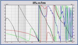
The 4th order elliptical filter EL4 isn't more complex than the EL3. Other component values, one capacitor extra in the woofer filter and one less in the midrange filter.
EL4 has a better outband reduction of 40 dB, the sum response of the targets is flat and the target phases are aligned perfectly.
XO schematic and plots of SPL, phase, impedance, xo transfers and groupdelay in attach.
Choosing for an elliptical concept, the EL4 is the best choice. All plans to improve EL3 will result in more complex filters, worse SPL flatness and deviations from target.
We can discuss about all later on.
Attachments
-
 20190115 MonkeyB EL4 450-2500 Groupdelay.JPG136.2 KB · Views: 359
 -
 20190115 MonkeyB EL4 450-2500 xo tranfers.JPG140.4 KB · Views: 362
 -
 20190115 MonkeyB EL4 450-2500 Phase.JPG165.1 KB · Views: 371
 -
 20190115 MonkeyB EL4 450-2500 SPL.JPG152.4 KB · Views: 384
 -
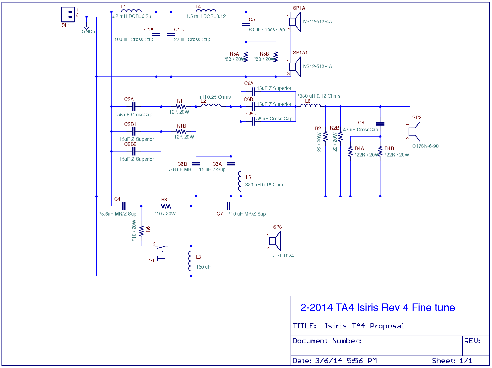
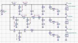 20190115 MonkeyB EL4 450-2500 Schematic.JPG218 KB · Views: 382
 -
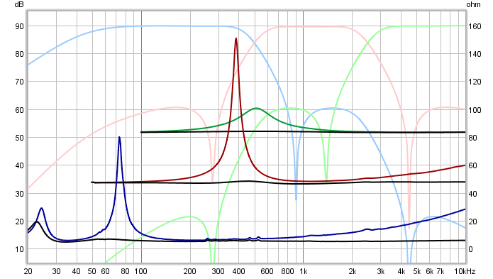
 20190115 MonkeyB EL4 450-2500 Impedance.JPG112.3 KB · Views: 114
Last edited:
The 4th order elliptical filter EL4 isn't more complex than the EL3. Other component values, one capacitor extra in the woofer filter and one less in the midrange filter.
EL4 has a better outband reduction of 40 dB, the sum response of the targets is flat and the target phases are aligned perfectly.
XO schematic and plots of SPL, phase, impedance, xo transfers and groupdelay in attach.
Choosing for an elliptical concept, the EL4 is the best choice. All plans to improve EL3 will result in more complex filters, worse SPL flatness and deviations from target.
We can discuss about all later on.
This looks interesting! Thanks Paul! I will try to empirically tweak my earlier simulation of the EL3 to in order to see how much I can improve the outband attenuation of the woofer. I will also do a version with this EL4 filter. Finally, I will try to make a "conventional" non-elliptic version for comparison. I will do this in Vituix because that's what I have and it also makes it easy to look at the off-axis response.
EL4 should be pretty good at any rate, I am not very familiar with the passive implementation of filters. But if EL4 is about equal to EL3 in complexity, I consider it (the choice) a no-brainer.
Juhazi, That was what I was proposing, to approach more equal acoustic xo slopes between the drivers, it has been common practice for years, the measured response of drivers is available, trying different filters and measuring to quality check the results equals more work, but it takes less time than arguing.
But if EL4 has the same components count as EL3, we do not have to discuss this further.
Edit:
And I was most certainly not suggesting a S. Harsch xo, but the material is interesting.
Last edited:
This dsp xo "world" is quite different than designing passives. Simulations are excellent but they need preicise measurements and lots of learning and understanding electronics too. I have decided to not even try to learn that!
Here we have lots of "old school" experienced designers of passive xos nad at HTGuide forum thre is "JonMarsh" aka "EvilTwin" who loves complex elliptic slopes. Isisris for example
Here we have lots of "old school" experienced designers of passive xos nad at HTGuide forum thre is "JonMarsh" aka "EvilTwin" who loves complex elliptic slopes. Isisris for example
A B3, 3rd order Butterworth, is an option. The Volt midrange with its 2nd order fall off at low frequencies and resonances at high frequencies, minimum a third order filter (acoustic) is required. Also for some excursion limitation at low frequencies.Finally, I will try to make a "conventional" non-elliptic version for comparison.
The B3 needs less components than the elliptical version, but it is more critical to make the design optimal. The phase difference between the drivers is 90 degrees and more sensitive for target deviations. On that point the even order filters are more easy to use.
In attach the EL4 targets used for the passive filter design, that can be useful in Vituix also. While tweaking it is important to stay around the targets, also outband. Timing will be affected between the filtered drivers compared with the target behavior and such filters will tend to sound blury and colored. Therefore I am not a fan of tweaking and adding circuits to improve outband reduction of the EL3 for example, compared with EL3 targets, that are different.
Attachments
Last edited:
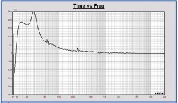
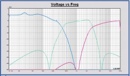
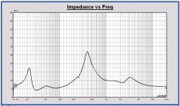
Will mean most drivers change subjective character to the better using resonance plus inductance compensation networks to linearize drivers impedance and experience is that is also the case using a active XO system, so suggest for these trials with miniDSP to find the optimal XO topology that add those components so that sonic improvement is also present for the active trial setup and those components shall be used anyway down the road, also for the subjective worry about the port such a network can make a change.
Below is the visual linearization that Paul use for the 3 times resonance compenzation networks plus 2 times inductance networks:
Below is the visual linearization that Paul use for the 3 times resonance compenzation networks plus 2 times inductance networks:
Attachments

Byrtt,
For the EL3 biquad miniDSP version I made for Matthias, the voltage transfers of the passive xo are chosen as the filter targets. In that way it is inclusive the influence of the impedance compensation networks. It was the reason we did it that way to have an exact copy of the passive filter version in the miniDSP.
For the EL3 biquad miniDSP version I made for Matthias, the voltage transfers of the passive xo are chosen as the filter targets. In that way it is inclusive the influence of the impedance compensation networks. It was the reason we did it that way to have an exact copy of the passive filter version in the miniDSP.
- Home
- Loudspeakers
- Multi-Way
- Open Source Monkey Box