I am actually surprised how well the models are able to reflect the real-world measurements. I guess I'll leave the bass-reflex tuning as it is now.
In the meantime, I have started a webpage to keep the relevant data in an organized way. Or at least I'll try. I would have preferred to do a Wiki here on diyAudio, but it seems the Wiki is not working for a while. The webpage is here.
Wow, very interesting this webpage, very practical!
I will look to the basreflex simulation if a better impedance fit on the measurement can be realized, but we are already very close to a correct low frequency SPL curve, to be used for further design.
Yes I agree, but till now I still haven't found a similar package with the same capabilities for a reasonable price.Leap is certainly a very good piece of software. Not saying otherwise.
But since development is halted for obvious reasons, probably better to get used to something else.
It should be a big advantage also that more people should use the same package to compare results etc. But I don't have a good solution at this moment.
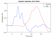
Ok, I am working to get the basic acoustic measurements done. Here's the time offset between the mid and woofer. The delay of the woofer relative to the mid is about 0.115 ms, so the acoustic center of the woofer is about 39 mm behind the mid. This is negligible compared to the wavelength of the intended x-over frequency, so there's nothing to worry about.
Attachments
One less thing. ")
I'm thinking about xo now.
What about 2nd order Bessel for the bass/mid, and a little bit higher order Elliptic for mid/tweet?
It would probably be a sensible compromise that keeps the amount of components down where they are most expensive (low freq), and sharp xo point with more complicated filter but less expensive components, higher up, where it would be nice to have the sharp roll off.
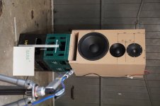
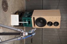
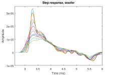
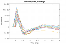
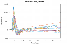
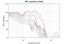
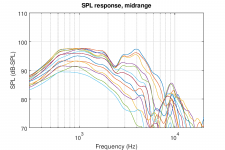
Here are the acoustic measurements of the drivers in the Monkey Coffin prototype box (20181219). I measured the drivers with the microphone 1m away from the baffle and on the height of the drivers (the anechoic part is therefore a little bit different for the different drivers). All measurements were done on-axis and horizontal off-axis at 0°/15°/30°/45°/60°/75°/90° "inside" and "outside" (see attached photos to explain the meaning of "inside" and "outside").
I calculated the anechoic SPL response and applied 1/4 octave smoothing to help the clarity of the plots. The raw impulse response data (TMD/ASCII files) and the processed SPL response data (FRD/ASCII) files are attached.
Edit: the "wall" you see in the photos is the garage door. While it does not look like it on the photos, it is more than 1m away from the drivers, and it does no harm to the anechoic part of the impulse response (which is limited by the echoes from the floor and the ceiling). I confirmed this by opening the door and repeating some of the measurements.
Attachments
-
 inside.JPG822.9 KB · Views: 311
 -
 outside.JPG845.3 KB · Views: 299
 -
 woofer_step_response.png44.4 KB · Views: 101
 -
 mid_step_response.png48.5 KB · Views: 104
 -
 tweeter_step_response.png43.4 KB · Views: 132
 -
 woofer_SPL_response.png56.7 KB · Views: 142
 -
 mid_SPL_response.png58.9 KB · Views: 281
 -
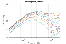 tweeter_SPL_response.png56.6 KB · Views: 307
Last edited:
I'm thinking about xo now.
What about 2nd order Bessel for the bass/mid, and a little bit higher order Elliptic for mid/tweet?
It would probably be a sensible compromise that keeps the amount of components down where they are most expensive (low freq), and sharp xo point with more complicated filter but less expensive components, higher up, where it would be nice to have the sharp roll off.
Sharp roll-off filters have their advantages and disadvantages. The same is true for slow roll-off. What do we need, and why?
Steep filters are useful when you need to keep a nasty cone breakup at bay. Or to keep the overlap between drivers as narrow as possible. But they sometimes mess up the time-domain response badly. And they take many parts in the signal path. The parts in the midrange filter will pile up!
I am a fan of clean time-domain response. My gut feeling is that we should try to start with simple filters and see how far we get. We can always make it more complicated along the way. I am pretty sure that will be happening in one way or another anyway...
I'd suggest to start with the woofer / midrange section first. The tweeter implementation is still somewhat open, as I'd like to see what we get from the waveguide design that augerpro is cooking up for us.
Hi Matthias,
Great, well done. A lot of information available now to start with and to investigate the behavior.
Maybe we have to start with the on axis SPL of each driver to make frd's for X-over design.
Also this, the coming period I will have less time to work on this project. Today the cabinets of my own speaker, I am currently working at, will be delivered. But I will do my very best to take as much time as possible for the Monkey Box.
Kaffimann,
I come back on the xo part in a later post. I have some comments too.
Great, well done. A lot of information available now to start with and to investigate the behavior.
Maybe we have to start with the on axis SPL of each driver to make frd's for X-over design.
Also this, the coming period I will have less time to work on this project. Today the cabinets of my own speaker, I am currently working at, will be delivered. But I will do my very best to take as much time as possible for the Monkey Box.
Kaffimann,
I come back on the xo part in a later post. I have some comments too
....I will have less time to work on this project. Today the cabinets of my own speaker, I am currently working at, will be delivered...
Well, if you get the cabinets delivered it means you're already done with the whole design process. Just mount the filters and the drivers, done in one afternoon
. Then you can continue your important design work for the Monkey Coffin while listening to your new speakers. We need you!I tried to listen to the Monkey Box woofer for a bit. Of course there is a lot of shout and no treble, but the bass... the bass... mmmmhhh, quick and articulate!
I don't see frd's in attach till now ??
Oooops, the ZIP file did not upload. Seems it's bigger than what diyAudio likes. I put it on the website so you can download it here.
The OB fanatics can go lay down, they have probably never heard a proper vented box and might not be ready for it.
Great to see some pictures Matthias, you just lifted the thread to the next level
Edit:
I had to mark the thread for 5 stars now, the progress is very good, and each obstacle is countered with team effort. Fantastic thread guys!
And big thanks to Matthias for doing the actual work!
Great to see some pictures Matthias, you just lifted the thread to the next level
Edit:
I had to mark the thread for 5 stars now, the progress is very good, and each obstacle is countered with team effort. Fantastic thread guys!
And big thanks to Matthias for doing the actual work!
Last edited:
I had to mark the thread for 5 stars now, the progress is very good, and each obstacle is countered with team effort. Fantastic thread guys!
Yep
And big thanks to Matthias for doing the actual work!
Thanks for that!
I just realised the SPL curves in my previous post were offset by +3 dB. I recently made some changes to the calibration code in MATAA, and it looks like I had a factor 1.414 too many. I fixed this now and replaced the ZIP archive with the correct data. Please delete the old file and use the new one.
Matthias,
I am working at the frd curves on axis.
The following questions now:
1. how sure are you that the absolute SPL level you measure now is accurate? +/- 1 dB, +/- 0.5 dB?
2. how accurate is the distance from the front baffle? 1.00m exact?
Because in my trials for an accurate splicing both with woofer and midrange, it looks like your measurement is about 1.0 to 1.5 dB higher than the accurate absolute SPL level.
I use driver models based on your impedance measurements, I did post them earlier.
Remark that measuring at 1.00m or at 1.10 m is 0.83 dB SPL difference.
Therefore my questions
Edit: Oeps I just missed your last post
Ok I use new zip. But I expect the level will be too low then, I let you know...
Last edited:
how sure are you that the absolute SPL level you measure now is accurate? +/- 1 dB, +/- 0.5 dB?
2. how accurate is the distance from the front baffle? 1.00m exact?
The data processing in the software is now accurate. I confirmed this by playing a sine sweep from 110 to 140 Hz in the nearfield of the Monkey Coffin woofer and used the RMS of the resulting microphone output signal as a reference (1.305 Pa(RMS) = 96.29 dB-SPL). Then I used the software to do an impulse response measurement (still nearfield), computed the SPL response from this, and took the average SPL level in the 110...140 Hz range: 96.28 dB-SPL. This confirms the calibration / normalisation of the FFT in the software is now correct.
However, there are some other factors that may introduce some uncertainties:
- I made a small mistake when I calibrated the gain of the amplifier. The voltage level at the speaker terminal is about 0.2...0.3 dB lower than what it should be.
- The microphone sensitivity is specified at 31.9 mV/Pa @ 22.1°C and 21% rel. humidity. I assumed this sensitivity is the same in my cold workshop, but it might in fact be a bit different.
- The microphone was exactly 100cm from the baffle. The acoustic centers of the drivers are a bit further away. The "depth" of the Volt VM752 is 28mm (baffle to where the voice coil meets the dome). If we assume this as the acoustic center for the Volt, the woofer acoustic center is 67 mm behind the baffle. That would be about 0.6 dB less.
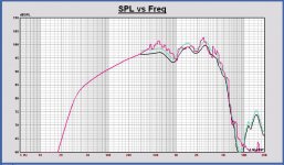
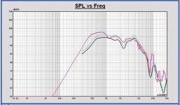
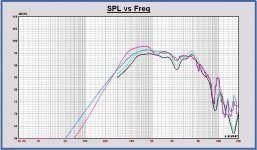
Look what my problem is for splicing curves. In attach woofer and midrange.
- the simulation in red
- measurement in black
- measurement + 1.5 dB in green
You can see there is a better fit with 1.5 dB more.
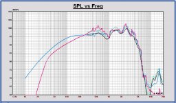
If I add also the driver on infinite baffle curve in the other plots in blue, it looks like we have to add 1.5 dB to the measurement.
It is important to do the splice with correct levels, otherwise there can be a difference of 1.5 dB between low and high frequencies.
Other remark, the Leap bafflestep boost level is always about 1 dB higher than a mls measurement with FFT window around 5 ms long.
Measurements in anechoic room with longer FFT window are fitting well on the Leap simulations. I think the reason is the short FFT window used in non anechoic rooms. In a way sound waves around the cabinet are not measured long enough. This is a thought now, I have to confirm this with some measurements in an anechoic room and playing with the FFT window length.
I don't understand completely the difference of the midrange measurement versus the simulation below 1 kHz. That is a big difference...
No problem to not use the simulation results, but we have to understand and be sure the measurement is correct. For sure there are some SPL smoothng effects caused by the 6 ms FFT window.
What do you think?
Is this stuff not too complex to post here?... please tell me then...
Concerning microphone sensitivity, it is very dependent on temperature.
This year, with my Clio setup I measured up to 2 dB difference at 27 degrees versus 20 degrees. 2dB more at the lower temperature...
There is an B&K article about this, I look for it.
Edit: At the start of every SPL measurement that I do, I first measure a calibrated driver.
That helps a lot to overcome the microphone sensitivity variation.
- the simulation in red
- measurement in black
- measurement + 1.5 dB in green
You can see there is a better fit with 1.5 dB more.
If I add also the driver on infinite baffle curve in the other plots in blue, it looks like we have to add 1.5 dB to the measurement.
It is important to do the splice with correct levels, otherwise there can be a difference of 1.5 dB between low and high frequencies.
Other remark, the Leap bafflestep boost level is always about 1 dB higher than a mls measurement with FFT window around 5 ms long.
Measurements in anechoic room with longer FFT window are fitting well on the Leap simulations. I think the reason is the short FFT window used in non anechoic rooms. In a way sound waves around the cabinet are not measured long enough. This is a thought now, I have to confirm this with some measurements in an anechoic room and playing with the FFT window length.
I don't understand completely the difference of the midrange measurement versus the simulation below 1 kHz. That is a big difference...
No problem to not use the simulation results, but we have to understand and be sure the measurement is correct. For sure there are some SPL smoothng effects caused by the 6 ms FFT window.
What do you think?
Is this stuff not too complex to post here?... please tell me then...
Concerning microphone sensitivity, it is very dependent on temperature.
This year, with my Clio setup I measured up to 2 dB difference at 27 degrees versus 20 degrees. 2dB more at the lower temperature...
There is an B&K article about this, I look for it.
Edit: At the start of every SPL measurement that I do, I first measure a calibrated driver.
That helps a lot to overcome the microphone sensitivity variation.
Attachments
-
 Faital 12PR320 in monkey cab Leap vs. measurment.JPG140.2 KB · Views: 236
 -
 Volt VM752 in monkey cab Leap vs. measurment.JPG146.8 KB · Views: 240
 -
 Faital 12PR320 in monkey cab Leap vs. measurement vs. driver inf baffle.JPG150.1 KB · Views: 235
 -
 Volt VM752 in monkey cab Leap vs. measurment vs. driver inf baffle.JPG149.3 KB · Views: 234
Last edited:
This is the link to the B&K doc about microphones.
https://www.bksv.com/media/doc/be1447.pdf
At page 3-18 more about sensitivity dependence on temperature.
At first sight the microphone sensitivity is much less dependent on temperature than I see in my Clio system. There will be another cause for that.
https://www.bksv.com/media/doc/be1447.pdf
At page 3-18 more about sensitivity dependence on temperature.
At first sight the microphone sensitivity is much less dependent on temperature than I see in my Clio system. There will be another cause for that.
Let me start by saying that I am blown away by how well the measured and modelled curves match up! The only difference is the 1.5 dB offset you mentioned, which I can easily believe given my comments above, and the uncertainty related to the sensitivity change of the microphone with temperature (I have sent an email to Earthworks asking about this). Since the offset seems consistent for both the woofer and the mid, I'd say it's ok to just move both curves up by 1.5 dB for x-over modelling.
Hey I just realised the fundraiser for the Monkey Coffin prototyping was successfull! Someone donated the missing amount to fill up the bucket to the CHF 400 mark! Thank you very much!
I have spent about 10% of the money for the prototype box, so we still have a lot for x-over parts.
I have spent about 10% of the money for the prototype box, so we still have a lot for x-over parts.
Matthias,
Is it possibe to post the midrange measurement 0 deg with a much longer FFT window. That means inclusive reflections.
For a driver with a steep fall off to low frequencies, the SPL curve will become better at low frequencies. Reflections are averaged.
Sure, I can do that. Tell me which gating time and octave-smoothing you want. Or you can just take the impulse response (TMD file in the ZIP archive) and have a play with that until you get what works best for you.
- Home
- Loudspeakers
- Multi-Way
- Open Source Monkey Box