I was a bit surprised to see that this is actually a bit lower (31 Hz or so) than what the electrical impedance measurement suggested (35 Hz or so). Why is this? How is the acoustic tuning different from the electronic world?
For the nearfield measurement you probably use a much lower voltage on the terminals than with the impedance measurement.
What you can do is measuring the impedance with the same voltage as you use for the nearfield measurement and look then to the relation between impedance dip and nearfield SPL dip.
Other reason can be some obstacles close to port or driver for one of the measurements. And using exactly the same measurement condition for both measurements, height from ground, distance from wall, etc...
Mbrennwa, last time I mentioned the potential of low end frequency response was in post 351. "Someone" planned for this all along.
Edit:
A part of this is the resistive behaviour of the slot port.
...
Paul, this port tuning should be very similar to closed box in some ways. I expect some (audible but lower) output to just under 30hz.
Edit:
A part of this is the resistive behaviour of the slot port.
Last edited:
For the nearfield measurement you probably use a much lower voltage on the terminals than with the impedance measurement ... Other reason can be some obstacles close to port or driver for one of the measurements. And using exactly the same measurement condition for both measurements, height from ground, distance from wall, etc...
The voltages wer actually not very different, and I tried different voltage levels with both the impedance and the acoustic nearfield tests. The main effect of this was that the lower impedance peak dropped a little bit with higher driver level (due to increased damping by turbulent loss in the port). The tuning frequency did not change much, if at all.
I found a thread with a few interesting posts about the interpretation of bass reflex impedance curves. In particular, the following comment might explain what I observed:
The minima is the port tuning frequency in the absence of driver inductance ... its exact frequency (and that of the zero phase point) can be shifted away from the actual port tuning frequency by driver inductance ... close miking the driver and finding the minimum is the most accurate way to determine tuning frequency.
So I guess the acoustic measurement is more reliable when it comes to analysing the bass reflex tuning.
Mbrennwa, last time I mentioned the potential of low end frequency response was in post 351. "Someone" planned for this all along.
Yes, I know 😉 I just want to understand the (apparent) discrepancies between the different measurements. Once I get my new measurement microphone I'll do some reliable bass/nearfield tests with different port lengths, and see which tuning sounds best to my ears.
I guess that with the current port design, shorting the port separator panel just a little bit will result in a substantial reduction of the acoustic/effective port length. Shortening the port separator by 2-3 cm or so will remove most of the "around-the-corner" part of the port. Let's see how it goes... I also need to figure out a clever woodworking method to actually make the port separator shorter without messing too much with the whole box construction. The rear panel is removable, but everything else is glued in place.
Shortening the port will cause higher resonance, but the slot port is more resistive than round ports, so the effect may be less pronounced. I will try to dig out my sims to see what I was thinking.
Edit:
The main cause of the resistive behaviour is more likely increased surface drag, while turbulence on the other hand, is reduced significantly because of the increased surface drag.
Edit:
The main cause of the resistive behaviour is more likely increased surface drag, while turbulence on the other hand, is reduced significantly because of the increased surface drag.
Last edited:
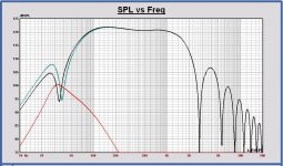
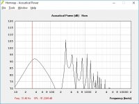
If measuring the driver nearfield, there is still a port SPL component that is added also. At 30 cm the nearfield SPL level of the port is about 15 dB attenuated. Making the SPL sum of the driver nearfied response and the port nearfield response - 15dB, results in a SPL with a lower dip.
In the plot, the nearfield of the driver (green), the nearfield of the port - 15 dB (red) and the sum of both (black). The dip decreases from 37.2 Hz to 34.5 Hz.
Indeed, the phase shift caused by the voice coil inductance also has some impact on the dip. The impedance dip is at 37.9 Hz and the SPL dip at 37.2 Hz.
So totally, the impedance dip is 37.9 Hz and the measured driver nearfield dip with the port close is 34.5 Hz.
In my simulation the port is tuned at 37 Hz. So, it cannot be measured exactly by the SPL dip neither by the impedance dip, if the port is positioned close to the driver and there is some phase shift caused by the voice coil inductance. You have to measure the excursion dip 🙂.
Attachments
Last edited:
Shortening the port will cause higher resonance, but the slot port is more resistive than round ports, so the effect may be less pronounced. I will try to dig out my sims to see what I was thinking.
Edit:
The main cause of the resistive behaviour is more likely increased surface drag, while turbulence on the other hand, is reduced significantly because of the increased surface drag.
But wouldn't surface drag coefficient be (almost) constant at different drive voltages? If so, drag would be linear with excursion. Also, as far as I understand this, the drag itself is a force that does not dissipate any energy. I am seeing a slight drop in the lower impedance peak with higher drive voltage, so there must be some non-linear process that increases damping at higher excursions. That's why I think it's turbulence.
If measuring the driver nearfield, there is still a port SPL component that is added also.
At 30 cm the nearfield SPL level of the port is about 15 dB attenuated.
I wouldn't call 30 cm "nearfield". For nearfield conditions, the microphone distance must be much less than the cone diameter.
I wouldn't call 30 cm "nearfield". For nearfield conditions, the microphone distance must be much less than the cone diameter.
Of course, but you misunderstand me. At 30 cm distance the SPL of the port is 15 dB lower than the nearfield SPL of the port, and I use the -15 dB SPL to add with the nearfield response of the driver.
Anyway there is some influence.
Mbrennwa, surface drag would be almost constant if direction did not change.
But this is a signal that changes direction and magnitude constantly.
Just started looking at the numbers just now, looking for the box dimensions.
Edit:
Found it in your post #282
Edit2:
Acoustic impedance should be ca 35.7hz, but the port should give some output to 30hz.
But this is a signal that changes direction and magnitude constantly.
Just started looking at the numbers just now, looking for the box dimensions.
Edit:
Found it in your post #282
Edit2:
Acoustic impedance should be ca 35.7hz, but the port should give some output to 30hz.
Last edited:
Uhm, no, please take a look at the drawing attached to post 346.
Regarding drag: I was referring to the drag coefficient that links the air velocity to the drag, thinking that drag = coefficient x speed-of-air. However, this linear relation is just plain wrong, so please forget about my earlier statement. Nevertheless, drag itself does not dissipate any energy and therefore does not provide damping; but drag causes turbulence, which leads to viscous energy dissipation, which provides the damping. So in the end we are talking about the same thing, I believe.
I hope the replacement microphone shows up soon so we can make some real progress 😀
Last edited:
What would you want to achieve?
How much shorter do you want it?
The corner section is part of the calculation.
How much shorter do you want it?
The corner section is part of the calculation.
Could you show your Hornresp setup with the corner section? With a bit of luck I might be able to implement it myself.
I am trying to understand what a given change in port length does to the tuning in terms of SPL response curve and group delay. With some model predictions at hand I could define a few port lengths to try in real life by measurement and listening with my ears.
I am trying to understand what a given change in port length does to the tuning in terms of SPL response curve and group delay. With some model predictions at hand I could define a few port lengths to try in real life by measurement and listening with my ears.
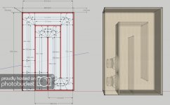
It is only a basic calculation, port length + material thickness + bend path length increase. For these low frequencies a bend will not change a whole lot of performance parameters, so they are for the most part ignored, but this is also why I suggested adding 1cm distance to the back wall, so any negative properties would be offset completely. Here is a picture i found in this post (there are lots of examples around in the various threads) that shows basic calculation of path length (the middle black line) +/- a little bit using common sense.
So in general you just imagine a line in the middle of the port and bend and use that for length. But add too much distance to the back wall and the bend is no longer part of the port, just like you suggested.
Edit: If you want a shorter port I would actually prefer making the port smaller, 32,4 cm * 4 cm = 129,6 cm2, and maybe get even lower FS. For a slot port this size it would not be so bad, because the highest air velocity would be the throat of the port, IE inside the box, the drag would make the peak air velocity change "sluggish" and make the problem more or less go away = no port chuffing.
Attachments
Last edited:
So in general you just imagine a line in the middle of the port and bend and use that for length.
Well, yes, and no. The cross section of the port is larger at the entry to the bend than at the main part of the port. The cross section even increases along the bend and then reduces to the main port section. This will give a different behaviour than a port with constant cross section.
But add too much distance to the back wall and the bend is no longer part of the port, just like you suggested.
Yup. But there is something in between "no bend at all" the "full bend" as it is now. Since I may end up in this in-between-situation I was wondering if the bend geometry is part of the model. It guess the geometry of the port entry (the bend) is not in the model.
1. Yes, but for a port this slim, there are some negative properties of not having a slightly wider transition this is why I wrote: "For these low frequencies a bend will not change a whole lot of performance parameters, so they are for the most part ignored, but this is also why I suggested adding 1cm distance to the back wall, so any negative properties would be offset completely."
2. The geometry is for the most part ignored, but again, for a port this slim there are some downsides to having a too narrow gap at the bend. The path length is accounted for and there is a slightly wider distance to back wall for compensation. If the box was deeper it would be better for a port this size, I think a smaller port is better for this box to lower the group delay peak further down the frequency range, the box is good, just not optimal. This is part of the compromise, -3db should be around 40hz with the box you built, and which is closer to the design goal.
Edit:
Before you begin cutting away port material, you could try to wedge in a board of 0,6-0,8mm material top of the port in it's length, use three strips of material near sides and the middle, to wedge it in place along the length. Only to see if you prefer a lower tuning before it's too late to try it. End the new material ca 5mm before the internal port end.
Edit2:
I remembered you made the back wall removeable, you could just use screws through the top of the port to attach a board of material, would be much faster.
Last edited:
... Did I kill the progress?
Not intending to be difficult, just want to make sure you try the various options before making any final decisions on what "sounds optimal".
Not intending to be difficult, just want to make sure you try the various options before making any final decisions on what "sounds optimal".
No, nooo, not at all!
I am just waiting to get the microphone replacement so that I can take a proper measurement of the box as it is now. Then I can start modifying the port / tuning to see what works best.
I am just waiting to get the microphone replacement so that I can take a proper measurement of the box as it is now. Then I can start modifying the port / tuning to see what works best.
Hi Matthias,
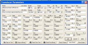
I did some more trials to fit the simulated impedance in the best way on your basreflex impedance measurement. I only get good fitting results if I increase the fs of the driver to 46 Hz. Otherwise the frequency tops are not at the right place.
If possible, can you do the free air impedance measurement again one time.
For me it is interesting to check the accuraccy of my simulation model, also to obtain the correct low frequency SPL.
In attach the current driver model used for simulation.
Attachments
- Home
- Loudspeakers
- Multi-Way
- Open Source Monkey Box