Thanks @fluid that is very close to what I want.
I don't plan on building a spin-o-rama but the idea is right. Appendix C indicates how they did it assuming the spherical surface pressure was measured. Easier with a robot.
I also thought there was another way to "approximate" it from the polars.
I don't plan on building a spin-o-rama but the idea is right. Appendix C indicates how they did it assuming the spherical surface pressure was measured. Easier with a robot.
I also thought there was another way to "approximate" it from the polars.
Have a closer look at Vituix, that is not just for simulation, the power and DI calculations can be done on actual measured data although it is geared to multiway design rather than single mic overall measurement. I'll check Sound Reproduction to see if there is any hints in there for guestimations.
Yeah vituixcad will show DI and power response from relatively simple horizontal and vertical measurement data which can be done rather fast at home with single mic by rotating the speaker whilst keeping the mic at fixes location. With large speakers, I think it is easier to move the mic. Either way VituixCAD will do the math ")
Toole video here says inverse of DI is quite good approximation of power response YouTube
Toole video here says inverse of DI is quite good approximation of power response YouTube
Thanks for the suggestions and links. After some reading .....
Interesting, looks like its still a development project. You have to compile your own code and it looks like it favors HolmImpulse input format.
I have scanned the thread for DI and PR. The method was discussed at post VituixCAD and seems to use method comparable to the paper by Tylka at https://www.princeton.edu/3D3A/Publications/Tylka_3D3A_DICalculation.pdf
As soon as I saw the graphs I knew I had seen this before in Toole's Sound Reproduction. Thanks for the video link.
I like the concept of EQ'ing a flat on-axis FR, measure the polars, then calculating a simplified DI (via VCAD?), then using the mirror image as the approx power response.
Now I need to build a fixture to pivot the speaker on the baffle centerline to make Hpolar measurements easier.
Might this offer some inspiration?
Klippel Near Field Scanner on a Shoestring
Interesting, looks like its still a development project. You have to compile your own code and it looks like it favors HolmImpulse input format.
Have a closer look at Vituix, that is not just for simulation, the power and DI calculations can be done on actual measured data although it is geared to multiway design rather than single mic overall measurement. I'll check Sound Reproduction to see if there is any hints in there for guestimations.
I have scanned the thread for DI and PR. The method was discussed at post VituixCAD and seems to use method comparable to the paper by Tylka at https://www.princeton.edu/3D3A/Publications/Tylka_3D3A_DICalculation.pdf
Yeah vituixcad will show DI and power response from relatively simple horizontal and vertical measurement data which can be done rather fast at home with single mic by rotating the speaker whilst keeping the mic at fixes location. With large speakers, I think it is easier to move the mic. Either way VituixCAD will do the math
Toole video here says inverse of DI is quite good approximation of power response YouTube
As soon as I saw the graphs I knew I had seen this before in Toole's Sound Reproduction. Thanks for the video link.
I like the concept of EQ'ing a flat on-axis FR, measure the polars, then calculating a simplified DI (via VCAD?), then using the mirror image as the approx power response.
Now I need to build a fixture to pivot the speaker on the baffle centerline to make Hpolar measurements easier.
Attachments
Last edited:
the ANSI / CTA 2034 standard aka "spinorama" this will show you...
Turns out the standard has some errors, as has/had the Klippel scanner software and Vituix.
There is a thread on this in the AudioScienceReview forum.
Spinorama! (also known as CTA/CEA 2034 but that sounds dull, apparently) | Audio Science Review (ASR) Forum
Most of the errors are clarified, had to contact the primary source researchers and have them check what the software actually did, as opposed to the published paper.
Next version of the standard may fix it.
Klippel has been informed of the problem, should be fixed.
Vituix has been fixed.
Best wishes
David
Last edited:
Might this offer some inspiration?
Klippel Near Field Scanner on a Shoestring
This has been continued on AudioScienceReview too.
DIY 3D Speaker Scanner - the Mathematics and Everything Else | Audio Science Review (ASR) Forum
Some really nice work by the OP that advances the discussion well past what the DIY thread reached.
So well worth a look.
Best wishes
David
Last edited:
I was wondering if another horn would allow a better fit for my MF BP.
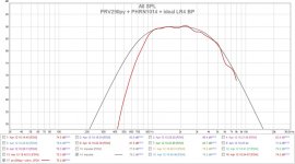
I hooked up another PRV290py to a PHRN1014. The first sweep sounded very wrong with abnormal squelching and chirping. I have had this with other drivers that were "sticking". I don't know how common this is.
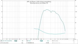
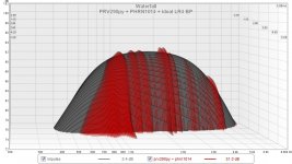
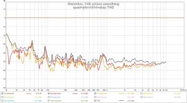
The initial FR and THD are shown below. The the 3rd pic is after 5 min of about 1 watt of white noise through the LR4 BP to wear in the driver. It still needs more "break in" but the trend is good and this should eventually be -50dBr like the other driver. Not sure if this is from surface roughness or dust.
.
I hooked up another PRV290py to a PHRN1014. The first sweep sounded very wrong with abnormal squelching and chirping. I have had this with other drivers that were "sticking". I don't know how common this is.
The initial FR and THD are shown below. The the 3rd pic is after 5 min of about 1 watt of white noise through the LR4 BP to wear in the driver. It still needs more "break in" but the trend is good and this should eventually be -50dBr like the other driver. Not sure if this is from surface roughness or dust.
.
Attachments
.. another horn for midrange
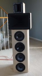
A few measurements after changing the midrange horn to a PHRN1014. I've seen these horns used in 2way EconoWave designs but probably crossed higher than I do. They are suppose to load down to 500Hz. I still have to measure the polars.
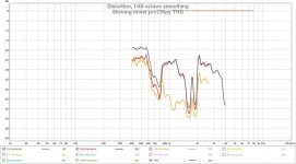
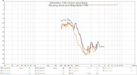
The horns where shuffled to time align them and then system EQ'd to get it mostly flat. After running it for another 5 hrs on music, the new driver THD is close to where it should be. The THD is still 5dB higher @850Hz (small bump) but the rest seems to indicate the driver is working properly now. It sounds OK now, even on the sweeps.
It's clear the driver would need several dB more EQ to follow the LR4 low side. This is about the same PRV290py driver limit as seen on the SH402 horn. I actually do EQ at the system level so the woofer picks up the shortfall and it effectively crosses at a slightly higher freq.
A few measurements after changing the midrange horn to a PHRN1014. I've seen these horns used in 2way EconoWave designs but probably crossed higher than I do. They are suppose to load down to 500Hz. I still have to measure the polars.
The horns where shuffled to time align them and then system EQ'd to get it mostly flat. After running it for another 5 hrs on music, the new driver THD is close to where it should be. The THD is still 5dB higher @850Hz (small bump) but the rest seems to indicate the driver is working properly now. It sounds OK now, even on the sweeps.
It's clear the driver would need several dB more EQ to follow the LR4 low side. This is about the same PRV290py driver limit as seen on the SH402 horn. I actually do EQ at the system level so the woofer picks up the shortfall and it effectively crosses at a slightly higher freq.
Attachments
Last edited:
Simply just too low xo. I would raise my hands and cross higher, and get nicer slope and lower distortion. But it is up to you to choose between better dispersion vs. lower distortion.
Eventually, that may be the case. If I keep using this compression driver (PRV290py) it would be certainly be happier at XO=900Hz and the woofers would have no problem either. I'm still trying to decide on the midrange dome/cone/horn and for now I can EQ everything flat and keep on listening.
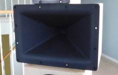
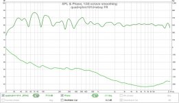
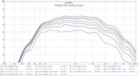
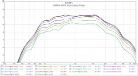
PHRN1014 midrange polars
I finally had a chance to measure the polars of these horns. Its driven by a PRV290py with LR4 BP. The system has been EQ'd to make it flattish on axis.
The horn is advertised as "exponential" but it certainly does not look it from the polars. It's suppose to load to 600Hz except I'm limited by the driver. The throat transition, flat walls and graphs remind me of OSWG. It looks fairly constant in the midrange where I'd use it. It sounds good as well.
Attachments

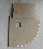
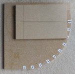
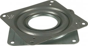
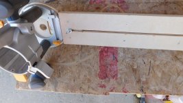
Hardware stores are open and I had a chance to build a simple fixture for horizontal polar measurements. Very easy to make using a turntable bearing fitted to a block that rests in the stationary base.
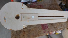
The speaker pivots about the baffle centerline. I used an adhesive plastic laminate to provide 2 smooth contact surfaces. I might change this to rollers between the surfaces if the remaining friction gets annoying.
.
The speaker pivots about the baffle centerline. I used an adhesive plastic laminate to provide 2 smooth contact surfaces. I might change this to rollers between the surfaces if the remaining friction gets annoying.
.
Attachments
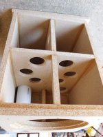
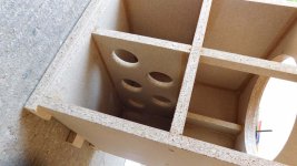
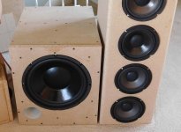
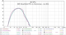
I also refactored my subwoofer to compare it to the BP6 using the same DCS305 driver.
The box volume (55L) lets me try it as either a BR or sealed (Q=0.66). The port pipe exits the front to make room placement easier (only one side radiates).
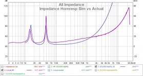
The sim uses the published T/S and the simple inductance model. The measurements are nearfield.
.
The box volume (55L) lets me try it as either a BR or sealed (Q=0.66). The port pipe exits the front to make room placement easier (only one side radiates).
The sim uses the published T/S and the simple inductance model. The measurements are nearfield.
.
Attachments
Great work!
That horn is definitely a constant directivity device. A copy of the QSC horn that became popular with the diy crowd about a decade ago. One of the best measuring waveguides around if you don't count diagonals.
Not really good below 1khz as you have noticed. Modern 1" drivers aren't really designed to be used that low. Might have decent luck with a BMS 5530.
A 1.4" exit driver would be much more at home below 1khz in a home setting. Something like this would match up nicely.
Eighteen Sound - Professional loudspeakers
- Home
- Loudspeakers
- Multi-Way
- Modular active 3 way - work in progress