I must be daft or somthing
Hi All;
Great work here with some really great insights and results. I am only doing simulations right now but am planning a build for the near future (Dec/Jan). It's all DSP so I can do whatever I want with biquads and canned crossovers and filters in Audio Weaver. Don't have enough horsepower for FIR arbitrary phase/amplitude filters unless I play with sample rates which I may do.
I will play with filler driver designs (which I have also learned about in this thread;THANKS to all) as well as conventional LR4 and BW4 etc designs. It's just a file and an upload once the drivers are measured.
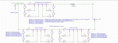
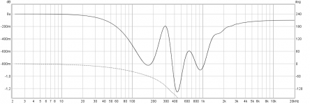
I am simulating biquads in SPICE and I can make the Butterworth/Bessel slopes but I cannot get the phase to make sense. The coefficients are from the Mini DSP spreadsheet. I am sure that they are correct. I have simulated a 2 way with a crossover at 375Hz (a FAST like xrk's) and I have the 1.3333ms delay in the tweeter path (1/375/2). Note that there are no drivers. The free space summation is an ideal summing node so driver response/displacement is not a concern (but I still can't get it to look like a Harsch response )
)
Intuitively what the simulation says makes sense. A constant delay (1.333ms) will result in huge phase wraps at higher frequencies. I simply cannot get the little phase ripple that you guys can make. 1.333ms at 1kHz is 480°, at 5kHz it's 2400°.
Am I doing something goofy or does what I am simulating make sense and I am just interpreting it incorrectly.
Thanks for any insight.
Matt
Hi All;
Great work here with some really great insights and results. I am only doing simulations right now but am planning a build for the near future (Dec/Jan). It's all DSP so I can do whatever I want with biquads and canned crossovers and filters in Audio Weaver. Don't have enough horsepower for FIR arbitrary phase/amplitude filters unless I play with sample rates which I may do.
I will play with filler driver designs (which I have also learned about in this thread;THANKS to all) as well as conventional LR4 and BW4 etc designs. It's just a file and an upload once the drivers are measured.
I am simulating biquads in SPICE and I can make the Butterworth/Bessel slopes but I cannot get the phase to make sense. The coefficients are from the Mini DSP spreadsheet. I am sure that they are correct. I have simulated a 2 way with a crossover at 375Hz (a FAST like xrk's) and I have the 1.3333ms delay in the tweeter path (1/375/2). Note that there are no drivers. The free space summation is an ideal summing node so driver response/displacement is not a concern (but I still can't get it to look like a Harsch response
)Intuitively what the simulation says makes sense. A constant delay (1.333ms) will result in huge phase wraps at higher frequencies. I simply cannot get the little phase ripple that you guys can make. 1.333ms at 1kHz is 480°, at 5kHz it's 2400°.
Am I doing something goofy or does what I am simulating make sense and I am just interpreting it incorrectly.
Thanks for any insight.
Matt
Attachments
Last edited:
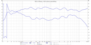
Think looks you probably close enough, filter is a compromise to transient perfect behavour summing two non symetrical out of phase minimum phase filter slopes plus add a physical delay to HF part, on axis sum is not as perfect as for example LR or 1st order slopes, for HARSCH filter sum have a cost in some more or less amplitude ripple.
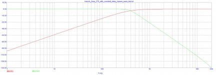
Error looks you view that summing ripple on a 1,5dB vertical scale and there it looks bit scary, i setup your project specs into REW and if you look below we can see vertical scales mean a lot : )
Error looks you view that summing ripple on a 1,5dB vertical scale and there it looks bit scary, i setup your project specs into REW and if you look below we can see vertical scales mean a lot : )
Attachments
Thanks Guys;
Brytt; I am not concerned about the amplitude ripple. I suspect that this gets lost in the noise of actual driver FR variations. Who knows; it might even help. It's the huge phase slope that I can't reconcile with the results presented here (small phase bump up to 60-90°). Again these are SPICE simulations. There are no drivers, offsets or lobing issues.
Charles; Thanks; will check what is available but this is not DSP that I have presented; it is a time domain based biquad simulated in SPICE (Micro Cap). Like the MiniDSP SW though I have many building blocks available including biquads that behave like the MiniDSP types. I do not have a subtractive delay however. There is a block for a two-way subtractive type crossover that i can play with.
Thanks
Matt
Okay phase was culprit subject : )
In REW i get the same phase wrap when i sum the two IR (impulse responses) with HF bandpass delayed 1,333mS because IR for the new summed bandpass continue sit 1,333mS delayed on timeline in IR window, but then one can re allign IR to time zero and phase then change to the characteristic HARSCH filter hump. Other method in REW that output the correct phase without one re alligning IR is instead of a delay to IR for HF band then set IR for LF band 1,333mS advanced in time, so wonder if you can do the same in remove the delay on HF band and try with for example a negative sign -1,333mS set for woofer, else try put a normal delay on both bands in front of their filter sections and see what happens, for example a delay of 1,333mS for LF band and then 2,666mS for HF band.
In REW i get the same phase wrap when i sum the two IR (impulse responses) with HF bandpass delayed 1,333mS because IR for the new summed bandpass continue sit 1,333mS delayed on timeline in IR window, but then one can re allign IR to time zero and phase then change to the characteristic HARSCH filter hump. Other method in REW that output the correct phase without one re alligning IR is instead of a delay to IR for HF band then set IR for LF band 1,333mS advanced in time, so wonder if you can do the same in remove the delay on HF band and try with for example a negative sign -1,333mS set for woofer, else try put a normal delay on both bands in front of their filter sections and see what happens, for example a delay of 1,333mS for LF band and then 2,666mS for HF band.
Last edited:
"The mid needs to be delayed from the woofer by 0.5/fc_low and the tweeter needs to be delayed from the mid by 0.5/fc_high. For my case, I used a 500Hz and 3500Hz XO points:"
This thread is interesting to me but I'm not drilling down through 51 pages at this point (I'll get there) 0.5/5000 is 2500 hz. I'm not understanding this part of the equation. Where does this convert to milliseconds of delay?
This thread is interesting to me but I'm not drilling down through 51 pages at this point (I'll get there) 0.5/5000 is 2500 hz. I'm not understanding this part of the equation. Where does this convert to milliseconds of delay?
"The mid needs to be delayed from the woofer by 0.5/fc_low and the tweeter needs to be delayed from the mid by 0.5/fc_high. For my case, I used a 500Hz and 3500Hz XO points:"
This thread is interesting to me but I'm not drilling down through 51 pages at this point (I'll get there) 0.5/5000 is 2500 hz. I'm not understanding this part of the equation. Where does this convert to milliseconds of delay?
Never mind. It's been a long day and I'm an idiot. I got this.
Hi Smirkr
Formula for @500Hz is dial in a acoustic slope for LP part 4th order Butterworth and for HP part 2nd order bessel slope, calculation for delay set to HP part is 1/500=0,002 x0,5=0,001, the first number "1" comes from frequency is cycles per second then we get 0,002 which is 2mS and times 0,5 we get a final result of 1mS.
For 3500Hz result is 0,000142, 142uS of delay for HP part.
Last edited:
Hi Smirkr
Formula for @500Hz is dial in a acoustic slope for LP part 4th order Butterworth and for HP part 2nd order bessel slope, calculation for delay set to HP part is 1/500=0,002 x0,5=0,001, the first number "1" comes from frequency is cycles per second then we get 0,002 which is 2mS and times 0,5 we get a final result of 1mS.
For 3500Hz result is 0,000142, 142uS of delay for HP part.
Yeah, after ruminating on that I figured it out. CPS is also a little off for this American. Hz seems to be the default term here. Thank you for your response.
Perhaps you could shed some light on an argument I'm having with my brother... I have a pair of MiniDSP 2x4's for my left and right speakers. According to my brother they will never sound right because each DSP has it's own internal digital clock and they will never be in sync. I've called BS on this. I'd love to hear other opinions.
Ha ha my view is think theoretical you both partly right there, he is right in isolated seen theoretical that clock is not 100% atom time in sync, you are right in it would not mean anything because drift in clock sync is so minimal a number compared to acoustics distance and wavelenght numbers for audioband frequency that it doesn't matter, probably drift is so small a number one could run say stereo subs from one miniDSP 2x4 unit and stereo fullrange transducer module from another miniDSP 2x4 unit without never notice any drift between sub and fullrange, but let each miniDSP 2x4 unit control per left or right channel will ensure any drift per sub verse fullrange module will never happen.
i haven't learnt other xo topology yet, just use straight harsch xo which already time aligned. so i thought about phase alignment with FIR, also to utilise more load on 2x4HD.
it seems it can work, enough for now. i'll revisit someday but if anyone already done it then it will be great to share.
it seems it can work, enough for now. i'll revisit someday but if anyone already done it then it will be great to share.
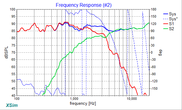
What if I told you guys that I was able to make a simple (2 inductors, 2 capacitors, 4 resistors) passive XO that resembles a Harsch XO and doesn’t need a stepped baffle and is easy to build and sounds great?
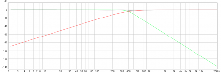
Here are the predicted XO curves, note the tell-tale sign of a Harsch XO in the slight dip in system response a bit below the woofer to the left of XO:
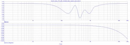
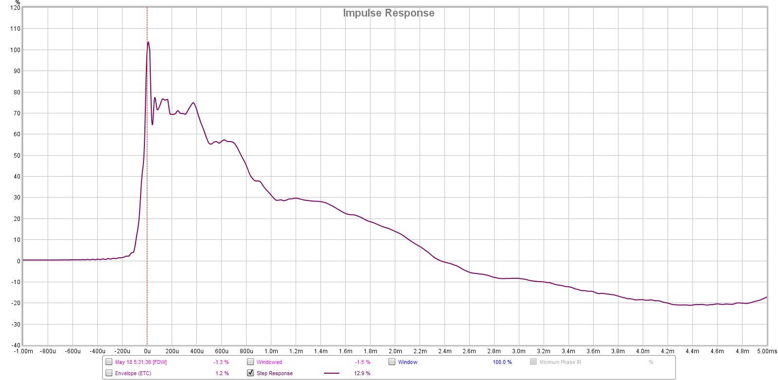
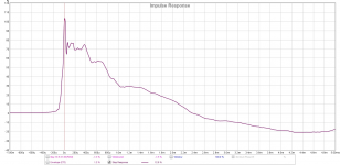
Here is the measured step response:
Here is measured acoustical phase - note that there is about a 55deg rise in the phase from the lower baseline to approximately where the XO point is.
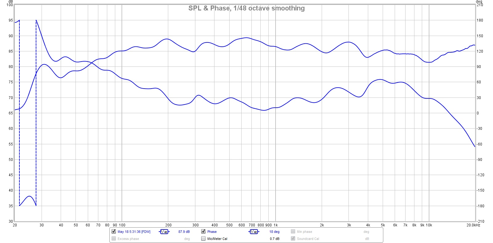
This was quite a surprise to me that it was possible, but made possible with a woofer that is wide bandwidth and a shallow commercially available waveguide on a dome tweeter.
Here are the predicted XO curves, note the tell-tale sign of a Harsch XO in the slight dip in system response a bit below the woofer to the left of XO:
Here is the measured step response:
Here is measured acoustical phase - note that there is about a 55deg rise in the phase from the lower baseline to approximately where the XO point is.
This was quite a surprise to me that it was possible, but made possible with a woofer that is wide bandwidth and a shallow commercially available waveguide on a dome tweeter.
Attachments

Last edited:
More info in new thread here:
https://www.diyaudio.com/forums/mul...using-ptt6-5-rs28f-waveguide.html#post6211942
https://www.diyaudio.com/forums/mul...using-ptt6-5-rs28f-waveguide.html#post6211942
Hi!
Sorry if the followings are noob questions but I have a few:
1. How I need to set the 2nd order Bessel filter in DSP if the 4th order Butterworth is set for example to 2000Hz? Q=0.58 that's fine but the cut-off is the same 2000Hz or i need to use the 1.27x factor due the Bessel target to get a -3dB point at 2000Hz?
2. How much the driver responses needs to follow their target responses from the crossover point to get good results? I ask because I didn't get better than +/-2dB around the xo point and the shallow sloping Bessel response causes cancellations far into the summed response even if I flattened the driver responses more than 1 octaves from the crossover point before applied the xo filters.
Thanks!
You have to go by what the measured acoustical response ends up being. The Harsch works for the measured response, not the electrically set one as the driver's own response combines with the electrical. Take for example, my Purifi PTT6.5 woofer above - I only used an electrical 2nd order but that combined with the natural falloff at -12dB/oct gives an overall 4th order falloff. So the answer is you need to input a theoretical response that you want of say 4th order at 2000Hz as an overaly in the graph. Adjust the DSP to achieve that. 1st flatten the responses and remove excessive peaks by wide (Q>1) gentle EQ via "cut the peaks" philosophy. Leave the dips alone. Then apply the electrical filter 2nd order, etc to achieve 4th order falloff at 2kHz. Match the overlay curve closely and you will avhieve a "textbook" Harsch XO. Dips and wiggles of 2dB or 2.5dB are OK - fixing them via EQ will add phase distortions that are best left alone for the higher goal of a flat phase response with 55deg rise to the right of the XO frequency.
- Home
- Loudspeakers
- Multi-Way
- S. Harsch XO