Regarding how many taps are folks using? Well that's a secret when JRiver locks ASIO driver up at 192Khz I/O 🙂 can say wesayso run small numbers and poor AMD A8-3870 that will be replaced because the other brand have much better single threaded performance and less power demand toggle in 20-30% area.
Are you calling my 65536 taps small numbers? It sure reads that way. 🙂
I know you aren't cause you know I run a Xeon quad core with hyper threading showing 8 cores total.
In all fairness I limit JRiver to 96 KHz because I can't feed my SP/dif connected DAC anything higher than that. With 6 channels of convolution running at 24/96 I'm still well below 10% while typing this message and having my email client open. Yes, I only have a single computer that does all. Strange for a former IT System Administrator. I also only have 2 amplifiers (both in use) and 2 sets of speakers. The ones I have build (two line arrays and two small ambient satellites) and the ones I parked in storage out in the garage. Again, strange for a DIY audio nut.
Last edited:
Ok, here another question I've got after a bit more playing:
When trying to eq phase I found I need to max out some of the sliders so I thought surely it can't need this much change.
I tried inverting the phase and it brought the phase trace a whole lot closer to zero so smaller changes were required.
This was a single driver so I didn't think phase would have mattered? I could understand if it was phase relative to another driver but one on its own.....
Once I build all the filters and crossovers and load these to the minidsp I should be able to see if there are any drivers out of phase when I do a complete system freq sweep, correct?
Thanks
Ok, here another question I've got after a bit more playing:
When trying to eq phase I found I need to max out some of the sliders so I thought surely it can't need this much change.
I tried inverting the phase and it brought the phase trace a whole lot closer to zero so smaller changes were required.
This was a single driver so I didn't think phase would have mattered? I could understand if it was phase relative to another driver but one on its own.....
Once I build all the filters and crossovers and load these to the minidsp I should be able to see if there are any drivers out of phase when I do a complete system freq sweep, correct?
Thanks
Here's the way 'seeing phase' works for me...I'm sure there are always better ways though 🙂
The single driver question.... the thing here is, all phase is relative...relative to some point in time. So the question becomes relative to what point in time.
Using acoustic reference timing, phase becomes relative to when the REW HF pre-measurement chirp hits the mic. Taken straight from REW help "When an acoustic timing reference is used individual measurements taken from the same mic position will have the same relative timing, allowing trace arithmetic to be carried out on the traces in the All SPL graph."
I put the 'delay relative to acoustic reference' that's shown in the measurement tab when you first make a measurement, in as the timing offset for the impulse response. When you do that, phase in the SPL & Phase tab moves to phase relative to that mic position, and is what I import into rePhase. (Oh, to view the phase smoothed, I use smoothing under the Graph tab, not IR window FDW which smooths, but also shifts timing.)
And yes, you will be able to easily see drivers out of phase when all put together.... it's one of the few things that is easy lol
nzlowie,
Guess you still at work out in camp and play around with synthetic exercises to educate, can share a little synthetic exercise with some structure support in form of target curves that maybe can help, also it should work in real world if measurement session is good enough quality. There is so many ways to reach right curves so mine is not any more right and better than other ways to think about it and execute procedures so think have an open mind and use ones brain under process helps.
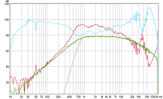
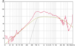
1. Exercise start in REW having one live measurement in red curve of 2426H/2370A combo, and two target curves where gold is first curve wanted red curve to be IIR EQed into and gray is final pass-band including XO point. Rephase creates happily those targets with following "Impulse Settings": taps=262144 windowing=rectangular, rate=important to set it to same as measurement, format=32 bits LPCM mono (.wav). After import target curve to REW use "Estimate IR Delay" to center IR.

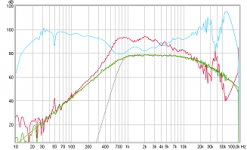
2. Blue curve is IIR EQ than when on "All SPL" tab then "Controls" is X (times) to red curve, hit "Generate" will bring us green curves IIR pass-band. To create EQ curve it was done in two steps where first was auto EQ into REW to help form that high pass 800Hz BW2 knee and exported those EQ settings to Rephase where second step of EQ was finalized and saved with same settings as target curves.
In general think having synthetic target curves is not bad as quality control to see we not way off, at other tabs here some synthetics points verse okay acoustics so far.

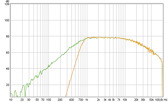
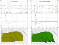
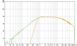
3. In green curve now have a known IIR pass-band 800Hz(BW2)-20kHz(LR2), phase turn at 20kHz roll off (system stop-band) is natural IIR and in mine view don't need any correction but do as one like, but 800Hz(BW2) IIR roll off and its phase turn we like to turn into 800Hz(LR8) linear phase and in we EQed raw driver to a known roll off knee its convenient use neat "compensate" mode in Rephase, that is mode set on "Minimum-Phase Filters" tab and will boost 800Hz(BW2) knee with IIR EQ so driver is flat amplitude and phase down to low frq and don't load such a setting real world because will blow poor coil in compression driver but after this go to "Linear-Phase Filters" tab and set 800Hz(LR) high pass which will steep high pass amplitude and leave phase flat.
Again at other tabs some quality control points synthetics verse not so far acoustics.
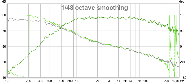
4. All corrections saved in Rephase from exercise can correct this driver when correction is saved as the format ones DSP support. Load it to DSP and recheck real world this pass-band acoustics with measurement at same spot in space perform as synthetics. If any variations these will need investigation and is probably because drivers raw response before EQed had amplitude response with room/object reflections that had some other distance to microphone than direct response from driver. Think some hints for measurement quality in REW is readable "Generate minimum phase" for a given measurement be it the raw driver performance or after EQed as seen in below green verse grey phase, if they not overlaid and follow same general directions other reflections add into response and where green phase makes curls not seen in grey is trouble area and probably only correctable by physical means.
Guess you still at work out in camp and play around with synthetic exercises to educate, can share a little synthetic exercise with some structure support in form of target curves that maybe can help, also it should work in real world if measurement session is good enough quality. There is so many ways to reach right curves so mine is not any more right and better than other ways to think about it and execute procedures so think have an open mind and use ones brain under process helps.
1. Exercise start in REW having one live measurement in red curve of 2426H/2370A combo, and two target curves where gold is first curve wanted red curve to be IIR EQed into and gray is final pass-band including XO point. Rephase creates happily those targets with following "Impulse Settings": taps=262144 windowing=rectangular, rate=important to set it to same as measurement, format=32 bits LPCM mono (.wav). After import target curve to REW use "Estimate IR Delay" to center IR.
2. Blue curve is IIR EQ than when on "All SPL" tab then "Controls" is X (times) to red curve, hit "Generate" will bring us green curves IIR pass-band. To create EQ curve it was done in two steps where first was auto EQ into REW to help form that high pass 800Hz BW2 knee and exported those EQ settings to Rephase where second step of EQ was finalized and saved with same settings as target curves.
In general think having synthetic target curves is not bad as quality control to see we not way off, at other tabs here some synthetics points verse okay acoustics so far.
3. In green curve now have a known IIR pass-band 800Hz(BW2)-20kHz(LR2), phase turn at 20kHz roll off (system stop-band) is natural IIR and in mine view don't need any correction but do as one like, but 800Hz(BW2) IIR roll off and its phase turn we like to turn into 800Hz(LR8) linear phase and in we EQed raw driver to a known roll off knee its convenient use neat "compensate" mode in Rephase, that is mode set on "Minimum-Phase Filters" tab and will boost 800Hz(BW2) knee with IIR EQ so driver is flat amplitude and phase down to low frq and don't load such a setting real world because will blow poor coil in compression driver but after this go to "Linear-Phase Filters" tab and set 800Hz(LR) high pass which will steep high pass amplitude and leave phase flat.
Again at other tabs some quality control points synthetics verse not so far acoustics.
4. All corrections saved in Rephase from exercise can correct this driver when correction is saved as the format ones DSP support. Load it to DSP and recheck real world this pass-band acoustics with measurement at same spot in space perform as synthetics. If any variations these will need investigation and is probably because drivers raw response before EQed had amplitude response with room/object reflections that had some other distance to microphone than direct response from driver. Think some hints for measurement quality in REW is readable "Generate minimum phase" for a given measurement be it the raw driver performance or after EQed as seen in below green verse grey phase, if they not overlaid and follow same general directions other reflections add into response and where green phase makes curls not seen in grey is trouble area and probably only correctable by physical means.
Attachments


Last edited:
Thanks Byrtt.
Yea I work in an office on mine site so I have plenty of time to research and study this topic.... Back in my room at camp I have a laptop with these programs as we can't run anything else on our work machines!
During my time at work I try and learn as much as I can (and ask toooo many questions!) so that when I get home I can put the theory into practice.
Really appreciate the help you guys give me. Much appreciated.
Hi Dave, hey I just realized I gave some incorrect advice earlier....
I said find the HF acoustic timing delay and use that for impulse offset for the HF, as well as the rest of the drivers.
That only works if you've already determined and set physical driver offset distances/delays, and are using loopback timing.
Here's what to do with acoustic timing: With the mic in the exact same position, the difference in acoustic timings shown on measurement tab between the raw drivers will be very close to the physical distance offsets. Determine the section differences vs the longest time measured, and in the miniDSP plugin, put those differences into the delays. So for example, REW says my HF acoustic delay is 1.33ms, and my MID delay, which is horn loaded and has a longer physical path, is 3.38ms. So I work to the longest time MID and add 2.05ms delay to the HF in minidsp delay. (3.38 - 1.33).
(Don't forget your HF will also need an extra 14.06ms delay figured in, to offset difference in taps, if using 2048 /2048 /698.)
Now when you measure the sections together with FIR files in place, SPL will either look smooth thru x-over or notched out. If notched, invert one in miniDSP.
After correct polarity is established, Phase should look smooth thru xover, but with maybe a smallish step up or down. Move delay in miniDSP sample at a time to dial in...it should be that close..
Something wrong..... Did some EQ on a bass channel file today but couldn't get it to load into minidsp. To start with I tried 2048 taps (min samples was 8192). Said I had too many coefficients but you are not allowed to upload more than 419 which is how many taps it said I have available. I used 419 taps in Rephrase when building this filter.
Any idea what I'm doing wrong.
Thanks
Sent from my Moto G (4) using Tapatalk
Any idea what I'm doing wrong.
Thanks
Sent from my Moto G (4) using Tapatalk
You need to allocate taps across the 8 channels first.
Assuming channels 1 thru 4 are Left, and 5 thru 8 are Right. And you are using 2048 / 2048 / 698 per side, in L,M,H configuration.....
Put 6 taps in 'Taps Used' for the unused channels 4 and 8. You will see 'Taps Available' increase. (Every channel requires a minimum of 6 taps.)
Then put 698 taps in High channels 3 and 7. That should leave 2048 for assigning to each of the 4 remaining channels...if that all adds up to 9600 😉
My plug in is the 96khz so only has 3400 taps available, so I tried using 750 taps setting. went back to rephase and regenerated the impluse file with 750 taps, tried to upload this to minidsp and still got the message: the system detected 4388 coefficients but you are not allowed more than 750 coefficients as specified in the taps used field.try again.
What's the difference between taps and coefficients?
Thanks
Sent from my Moto G (4) using Tapatalk
What's the difference between taps and coefficients?
Thanks
Sent from my Moto G (4) using Tapatalk
I thought they are the same thing....
make sure to unload the FIR file and send to dsp, before loading a new file.
That might be why you're getting strange numbers...files adding together??
And I would definitely use the 48K plugin...
make sure to unload the FIR file and send to dsp, before loading a new file.
That might be why you're getting strange numbers...files adding together??
And I would definitely use the 48K plugin...
Have changed to the 48k plug in. It still says there are too many coefficients. Seems the coefficients need to match the number of taps.
Only way to make this work is to set a real small number of taps in Rephase.
I'm doing something wrong for sure...
Sent from my Moto G (4) using Tapatalk
Only way to make this work is to set a real small number of taps in Rephase.
I'm doing something wrong for sure...
Sent from my Moto G (4) using Tapatalk
When in FIR Filter (in any channel) 4x8 or 4x8/96:
- choose File mode
- BEFORE you Browse/Load/Send to DSP your intended filter, you must enter manually the number of taps in the "Taps used" field , in the lower right corner above the "Taps Available".
- You need to enter the number which is equal to or higher than the number of taps your filter uses. Program will inform you that if you have "spare" taps unused, it will fill them as zero....
- After this, you can download and "Send to DSP", AND then unclick "Bypass"
- Lastly: tap=coefficient AFAIK
Draki
Last edited:
Thanks Dealing
Yea did that.... redid the rePhase with 1024 taps, set taps used to 1024 and selected the filter file. Same message, too many coefficients. Try again.

Sent from my SM-T800 using Tapatalk
Yea did that.... redid the rePhase with 1024 taps, set taps used to 1024 and selected the filter file. Same message, too many coefficients. Try again.
Sent from my SM-T800 using Tapatalk
Last edited:
Are the rePhase files 32 bits IEEE - 754 mono (.bin) ?
That's the only one I know to work in plugins....
That's the only one I know to work in plugins....
Thanks Dealing
Yea did that.... redid the rePhase with 1024 taps, set taps used to 1024 and selected the filter file. Same message, too many coefficients. Try again.
View attachment 597650
Sent from my SM-T800 using Tapatalk
The program "sees" your 1024-taps designed as 6067.75 taps! Did you check the correct file format needed for MiniDSP?
EDIT: Mark100 already posted the correct file format////
Cheers guys, I knew it must be something that I was doing wrong!!!
Wrong file formats!
Now I know it loads I'll try again....
Thanks
Sent from my SM-T800 using Tapatalk
Wrong file formats!
Now I know it loads I'll try again....
Thanks
Sent from my SM-T800 using Tapatalk
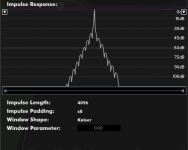
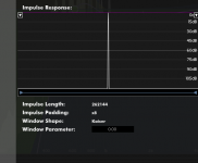
I agree with WESAYSO. For low frequency, low tap FIR is not recommended. 262144 is my current impulse length. That's the max number I can do with my computer, but I wish I can make it higher in the future. Digital technology is still very immature. 🙂
Attachments
Last edited:
FYI, Behringer has a b-stock UMC1820 for $235 at Ebay 182288043960
I bought the 1st and now need to order a mic. Only 2 refurbs since initial November batch has me optimistic.
I bought the 1st and now need to order a mic. Only 2 refurbs since initial November batch has me optimistic.
FYI, Behringer has a b-stock UMC1820 for $235 at Ebay 182288043960
I bought the 1st and now need to order a mic. Only 2 refurbs since initial November batch has me optimistic.
Is anyone have measured the UMC1820 rmaa performance ?
- Home
- Design & Build
- Software Tools
- rePhase, a loudspeaker phase linearization, EQ and FIR filtering tool