Oabeieo,
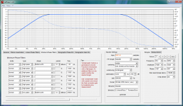
You can make sim exercises in Rephase and study what happens and learn from that, also one can generate files there and import them into example REW where they can be played around with making complicated math on "All SPL" tab. Opening Rephase without making any filters show a perfect wide bandwidth device from DC component to lightspeed, flat amplitude and phase all over.
For a given band pass phase verse frequency in minimum phase domain (IIR) in general is turning 90º per order as amplitude falls off, for high pass function phase starts goes lagging direction (slow lows) and for low pass function phase above cut frq goes advance direction, phase turn is halfway at cut frq (stopband).
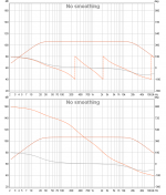
1. example below show audio system band pass 20Hz-20kHz with 2nd order roll offs, phase lag is half way +90º at cut frq 20Hz and 180º down at DC component, up at HF phase is in advance -90º at cut frq 20kHz and full 180º up higher.
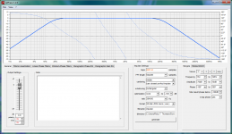
2. example show same system band pass but this time its a sum of three united pass bands with LR4 XO points at 300Hz pus 2kHz.
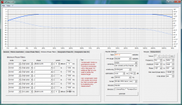
3. example is sim of power amp device 1st order roll off wide bandwidth 5hz-500kHz.
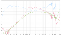
4. example is over in REW red curve is measurement of 2426h/2370a horn, blue curve is correction made in Rephase also gold target curve is made in Rephase, green curve is sum of math at "All SPL" tab commanding red curve times blue curve.
You can make sim exercises in Rephase and study what happens and learn from that, also one can generate files there and import them into example REW where they can be played around with making complicated math on "All SPL" tab. Opening Rephase without making any filters show a perfect wide bandwidth device from DC component to lightspeed, flat amplitude and phase all over.
For a given band pass phase verse frequency in minimum phase domain (IIR) in general is turning 90º per order as amplitude falls off, for high pass function phase starts goes lagging direction (slow lows) and for low pass function phase above cut frq goes advance direction, phase turn is halfway at cut frq (stopband).
1. example below show audio system band pass 20Hz-20kHz with 2nd order roll offs, phase lag is half way +90º at cut frq 20Hz and 180º down at DC component, up at HF phase is in advance -90º at cut frq 20kHz and full 180º up higher.
2. example show same system band pass but this time its a sum of three united pass bands with LR4 XO points at 300Hz pus 2kHz.
3. example is sim of power amp device 1st order roll off wide bandwidth 5hz-500kHz.
4. example is over in REW red curve is measurement of 2426h/2370a horn, blue curve is correction made in Rephase also gold target curve is made in Rephase, green curve is sum of math at "All SPL" tab commanding red curve times blue curve.
Attachments
Last edited:

Now for something completly different: I just found rePhase working with wine on Linux. So for now there is no reason for me to use a VM anymore
reGards
reGards
Last edited:
Wow thanks BYRTT. So I ran some sims and definitely see what your saying , what's funny is someone just told me and I now see why that is~ we should be using wrapped phase as a view mode primarily. Would you find that statement to be true as well. I think I've been over complicating it and trying to make more out of it. It's the whole degrees = time thing that confuses me but playing with these sims it starts to make sence.
thank you,
thank you,
Wow thanks BYRTT. So I ran some sims and definitely see what your saying , what's funny is someone just told me and I now see why that is~ we should be using wrapped phase as a view mode primarily. Would you find that statement to be true as well. I think I've been over complicating it and trying to make more out of it. It's the whole degrees = time thing that confuses me but playing with these sims it starts to make sence.
thank you,
Welcome and glad you got it so run sims as crazy because think its very educating.
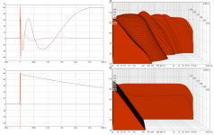
About wrapped phase its just a view mode as in below example which is the system band pass 20Hz-20kHz from post 1681 where there is LR4 XO points at 300Hz and 2kHz, with wrapped phase maybe phase looks flatter but it doesn't change reality that phase turn sum inside 20Hz-20kHz audio band is 900º (2x90º at system stop bands and 2x360º for XO points). Grey phase curve is the interesting XO-less one that Rephase can help build to improve transients and ringing 🙂
Attachments
Last edited:
I agree with BYRTT here, looking wrapped or unwrapped phase is nothing more than a preference. The phase plot itself isn't different. It's still the same information.
Also try to look at the other graphs within REW to see what changes there. It's all the same information, just presented differently.
These textbook examples might give you a better handle on what is happening. Try an IIR (PEQ) boost or cut in such an example and see how phase changes.
Also try to look at the other graphs within REW to see what changes there. It's all the same information, just presented differently.
These textbook examples might give you a better handle on what is happening. Try an IIR (PEQ) boost or cut in such an example and see how phase changes.
Last edited:
Welcome and glad you got it so run sims as crazy because think its very educating.
About wrapped phase its just a view mode as in below example which is the system band pass 20Hz-20kHz from post 1681 where there is LR4 XO points at 300Hz and 2kHz, with wrapped phase maybe phase looks flatter but it doesn't change reality that phase turn sum inside 20Hz-20kHz audio band is 900º (2x90º at system stop bands and 2x360º for XO points). Grey phase curve is the interesting XO-less one that Rephase can help build to improve transients and ringing 🙂
You have no idea how much this is helping me!
I agree with BYRTT here, looking wrapped or unwrapped phase is nothing more than a preference. The phase plot itself isn't different. It's still the same information.
Also try to look at the other graphs within REW to see what changes there. It's all the same information, just presented differently.
These textbook examples might give you a better handle on what is happening. Try an IIR (PEQ) boost or cut in such an example and see how phase changes.
Thanks wesayso, And that's a pretty good point you make right there because I have actually done that quite a bit like if I take a Iir peak filter and watch phase go down than go up above true 0 than go flat again , it does that because the time shift right? Time is a constant , so it can't be graphed straight when it has to be graphically "folded" if you will , right? It's just shows on the graph itself. Because as the peak goes down time is decreasing, and as the peak goes up time is increasing so it would show a increase above true0 because all thing come out at the same relative time . The frequency wave is than shifts in that time window. Or am I way off?
It's really hard to explain but I think that's how it's being displayed . And if that is the case that really really really helps me in knowing what's going on .
I think without a bit of Trigonometry and an understanding of radians and such it is hard to comprehend phase angle and its relationships.
Look at the degrees as "time information". However, frequency wave lengths do differ.
Look at group delay for the actual timing chart. Zoom in to see what happens. At high frequencies the actual time change will be small, The longer wave lengths in lower frequencies will show way more deviation in ms in case of a phase rotation.
Compare this with a PEQ cut at 50 Hz and 5000 Hz to get a feel for it.
Whether you use digital IIR/named crossover filters (e.g. Linkwitz-Riley, Bessel etc) or coils and capacitors, they will change the phase when they change the FR curve. So does the natural roll off of a driver.
This is still easy to see, compared to measurements that include a room. A reflection could add energy at one frequency and subtract (create a dip) at another. But if you move, the relationship in distance between the driver and the reflective surface changes too. So if one were to EQ that bump or dip out, it would only be valid for that single position where the measurement was recorded. In other words, it may make phase and FR in other positions even worse.
Last edited:
I think I'm finally starting to get this.
Yes okay. Low frequencies have a wider span in the time window because there's more distance from peak to peak , One cycle is one cycle whether it be at 20 Hz or 20,000hz , but the distance from Peak to Peak is a reflection on the time window for how long that frequency takes to complete one cycle . And in the acoustical world distance is time because of the speed of sound constant. group delay would be a smear in the time process caused by whatever is slowing it down , like a port in a box because it's a 1/4wave device. Because the time it takes inside the box and the port can't be added to the total time because it's trapped inside the box . Or delay from a crossover because a slope may be attenuating the frequency causing a delay in passband or stop band depending on if it's a HP or LP...
No?
I'm not getting the peak to peak description. Just figure out a 20 Hz signal is 20 cycles within a second. 2000 Hz is 2000 cycles within that second.
Peak to peak makes me think of woofers flapping to create sound. It will move a greater distance to create a higher SPL, but as long as its still moving 20 cycles a second it is still playing a 20 Hz tone. Care to explain what you meant with peak to peak?
It's tricky to explain this all without wording it terribly wrong.
I'm not getting the peak to peak description.
It is because peak to peak mean voltage or volume difference (or amplitude) and we read it in the 'vertical' plan, i think Oabeio take the max positive peak to the next max positive peak in the 'horizontal' plan, so he is talking about time difference from positive peak to the next positive peak . 😉
Don't use peak to peak to talk about time behavior Oabeio, it'll never be understood because Peak/Peak is usually used to determine amplitude behavior, not time.
I'm not getting the peak to peak description. Just figure out a 20 Hz signal is 20 cycles within a second. 2000 Hz is 2000 cycles within that second.
Peak to peak makes me think of woofers flapping to create sound. It will move a greater distance to create a higher SPL, but as long as its still moving 20 cycles a second it is still playing a 20 Hz tone. Care to explain what you meant with peak to peak?
It's tricky to explain this all without wording it terribly wrong.
Yeah I suck at explaining stuff. 😛
So , okay let me try this,
Let's say for whatever frequency,
What effect does positive phase have on the acoustical signal, and negative?
If something is let's say 90° too high ," the peak " (phase graph either in REw or rephase).. does it come first in time or after? It may seem like a dumb question but I just want to be sure . That might be a better way for me to get this.
Last edited:
Yeah I suck at explaining stuff. 😛
So , okay let me try this,
Let's say for whatever frequency,
What effect does positive phase have on the acoustical signal, and negative?
If something is let's say 90° too high ," the peak " (phase graph either in REw or rephase).. does it come first in time or after? It may seem like a dumb question but I just want to be sure . That might be a better way for me to get this.
I think the mathematical definition of a sinusoid and phase would be a better way:
https://en.wikipedia.org/wiki/Sine_wave
I think the mathematical definition of a sinusoid and phase would be a better way:
https://en.wikipedia.org/wiki/Sine_wave
Nc535 , thank you for sharing that,
So I guess hold on guys . I need to read this link all the way I was just skimming through it and discovered I need to learn more about this sinusoid first.
I don't know what a radian is and I get the feeling it's important for me to read this first and start digging the web on this sort of info.
Of course I'll probably do a bunch of searches and find the for dummies section but hey. I'll come back with something I'm sure 😛 😀
Nc535,
I just read it. And thought it through. Oh man! You answered the question I have been trying to grasp for some time now. And the whole time the answer has been mathematics.
That page completely caught me off gaurd because I didn't expect to have this big of revolution in thinking.
The radian and degree conversion, of frikkin course yes that solves these riddles in complete fulfillment. the circle (phase 0 to 360° Or 0 to 1000°) 0 meaning the time it starts and the degree depends on the circle. The circle for us is two halves of a wave form or more properly 1 cycle. But according to this radian thing the circle must me measured to see how big it is The same way you find The circumference of any Circle (2 pI r) , And for us the frequency or wavelength must be determined to make that measurement into degrees using the radian to degrees conversion.
This math allows me to work out on my own either an electrical distance or a acoustical distance with the same math. And distance = time in acoustical world because of speed of sound.
And believe me gang , I ain't no expert in 5min I got a ton of reading but literally in 5min I have a way now to understand what the heck these measurements mean when I take them when I'm looking at my speakers and asking myself ...... x speaker is x amount away from me and this other speaker is this other distance (a car) and work out for my self what's happening between the unequal path lengths at far as time difference and polarity between cycles (at least for cycles long enough for me to worry about) and read my silly measurements and get it. This is a big day for me I feel like such a nerd.
Last edited:
If the minimum-phase generated curve looks good then the real phase curve should not be a mess (that is unless your crossovers are a mess 😉 ).
You can play with the "time offset" entry in the measurement tab in rephase and see if it gets better.
You should end up with a phase curve that looks like the REW's minimum-phase one plus a few all-pass around your crossover points.
Also do not hesitate to play with polarity.
Hi POS
I've just started to look at this program again, slowly learning bits of it.....
I have some REW files that I can play with if you give me some basic steps, What IR window should I set?
From what I've picked up I would create a new crossover channel for each driver to be imported into my minidsp. correct? So I measure each driver without a crossover then set the crossover filter in rephase and tweak the phase of each of driver to zero. Correct?
Sorry for the basic questions but I haven't read a basic usage post so I'm just trying to put the pieces together!
This is a bit new to me... so if anyone could spare some time to walk me through the process I'd be most grateful.
Just let me know what info I need to show.
Many thanks Dave
Hi Dave,
Pos, and so many other fine folks have helped me on a bunch of different topics. Maybe trying to post about beginning with rePhase is a way i can contribute back.
If we were skiing 'rePhase mountain', I'd consider myself an intermediate skier, .....so don't take my advice for more than it is.....😉 Alot of trail still remains over my head.
Anyway, I tend to think there are two fundamental starting approaches.
The first, driver by driver, the one you mentioned, is more for the speaker builder, that doesn't have any x-overs already in place.
The second, system level, is for someone who has a speaker system running with x-overs already in place, be the x-overs passive or active. I'm going to leave this approach alone because....
My approach is driver by driver. It starts with a raw measurement of each driver section in as reflection free environment as possible. Outdoors is best, but often speakers are hard to set up outside. Indoors, I think that's where IR windows come in...trying to get the equivalent of a reflection free measurement....a few brief words on this later.
Ok, I'm going to assume you have your measurements and a pretty good idea of the x-over points you want to use, and move on to how i would handle building the driver files in rePhase.
First step is to apply parametric eq to smooth out the magnitude response. When response is smoothed, it also smooths and flattens phase, so you want to do this before even looking at phase IMO. The only caveat is knowing what response in the measurements can be smoothed (reflection free speaker variations) and which can't (room reflections). That's beyond the scope of my attempt to explain here. Suffice it to say, the lower the samples you use in IR windowing, the greater the chance you're not trying to eq the room. Wesayso and BYRTT offer good explanations worth searching for, both recently and in numerous posts here and there.
I find it helpful to smooth magnitude thru and beyond the x-over point, thru at least -20dB and more if possible. This assures good summation thru the critical region. Just don't try to force response when the driver just plain can't go there...IOW, stay reasonable with electrical correction that may indeed be nothing but electrical.
Then time to look at phase. Kinda do an overall assessment...how far is it from flat at 0 degrees? Does inversion help? The time offset under the measurement tab moves the right side of the trace up and down. Filters Linearization various alternatives change slope / shape / position. Used in combination with time offset what gets you closer to flat at zero. There's also 'compensate' under minimum phase filters, along with all-pass filters.
It just takes a lot of experimentation IME....here's where I'd love some pointers !
One place I always start though is with Filters Lineaization where the chosen filters kinda match the response of the driver...IOW, if my mid driver rolls off on the low end at 100Hz, I try different filter types and order all using 100Hz first, to see which one is worth investing time in...
Final phase adjustment step is parametric phase . Do make it the final minor step hopefully, and know it can't pull off magic on the ends of the passbands where the drivers are beginning to run out of their range.
Then it's time to apply the x-over. I use complementary linear-phase crossovers....makes life easy.
Once you get your rePhase file for the drivers generated with the looks you want, go measure the drivers one by one with their files in place. Adjust files as needed.
At this point, we hope to have a set of drivers that all have pretty smooth magnitude and phase though their passbands, and flat phase through the x-over summation regions.
If phase is flat at zero degrees for all of them it just becomes a matter of....
.... putting them all together, only needing to set polarities, time delays, and levels.
You may find you need to invert polarities in rePhase if your equipment doesn't allow such section by section... which is no worry.
If you are using REW, one tip is to start with the HF section. REW uses a HF signal for acoustic timing reference, and will easily locate the HF section. Put that time in impulse response offset...(and don't change it with Estimate IR or min phase or whatever 😀)
Because you're going to put that same time offset in for the rest of the driver measurements....that way they will all show phase relative to the same one point in time.
Good luck !...hope this helped ! mark
Thanks Mark
An excellent reply, I'm away at work until next week so won't be able to do any measuring but I'll try to keep building the process in my head. (Using my laptop and REW data back at camp)
So, measure each driver in REW using the smallest IR window to eliminate reflections. Any idea of starting point?
Then smooth these in rephase.
So I remove all cross over filters and eq that are loaded to the minidsp already?
Once I have completed the smoothing, including the cross over area I start looking at phase.
Will have to have a play with the filters before I know what questions to ask but really we're just using these filters to complete the individual driver response (cross overed).
Still a bit unsure about the impulse settings where the actual filter is created. Taps, windowing and optimization, how do we select these values?
Once each driver filter is created these are uploaded to the minidsp for the appropriate driver channel.
Once again thanks for your assistance, time to have a play with the data I have on hand back at camp so get ready as I'm sure there are more questions coming!
Slowly getting it....
Cheers
How hard would it be to make a app or UI or some sort of software that does the following
Let's put on our car audio hats for a moment and think about a car environment.
The room is a big metal box and the seat is in a corner. So what we have available today is
Signal delays right, so we add a delay to the closest speaker and that fixes most of the problem. But like we all know it only time aligned for one frequency.
What if someone make a UI that you could plug in the path length difference into and it would give you a correction based purely from PLD that has a phase and time offset that we could use that would be a time and phase correction. I don't know how such a thing could generate a filter with delay and phase so I would imagine it would have to output a phase correction along with a delay setting to be plugged in.
Like if I told this software my crossover , passband, and PLD between pairs of speakers could there be a way to get a better way than just adding delay. Kinda like time alignment v.2 ..... I think it would be sweet because there would be no measurements needed so no reflections, and would be a pretty accurate way to get at least a coherent phase electrically being all things equal.
I know there's drawbacks to this idea like the difference in phase due to axial radiation from having one speaker on different axis than other and reflections , however it would be cool to try to make something that would do it.
Could rephase generate at least the phase portion if I used raw delay? How would someone go about doing that. Or is measurements way still better and I'm over thinking it?
Cheers
So, measure each driver in REW using the smallest IR window to eliminate reflections. Any idea of starting point?
Then smooth these in rephase.
So I remove all cross over filters and eq that are loaded to the minidsp already?
Still a bit unsure about the impulse settings where the actual filter is created. Taps, windowing and optimization, how do we select these values?
You're very welcome !
I have to admit i don't really rely on IR windows very much, probably because I am still learning how to use them properly.
I do think you don't necessarily need to use IR windows, IF you can make reasonably good reflection free measurements to begin with,..... which is what I try to do.
Whether using IR windows or not, just make broad strokes with eq at first...attack the biggies...load the file...see how the measurement changes...
Maybe the best way to start with broad strokes is use FDW on 5 cycles (about 1/6 oct) and eq to that. I find that's a little overly smoothed to work with, but then again I've started with measurements I trust to be a little more reflection free. So I'm ready from the gitgo to eq at greater resolution, say 1/18 oct or so.. but not sure it ever pays to eq past that.
The big thing is, don't expect to be able to do everything right on the first pass. I'd recommend broad eq brush strokes until you get the hang of building files, loading them, and making new measurements to see how the files pan out.
# of taps to use is more a function of how many do you have to work with, how many drivers, and cross over points. I've found simply using Hann to be a good starting place, along with moderate optimization.
Which miniDSP box are you using? What are the x-over points?
- Home
- Design & Build
- Software Tools
- rePhase, a loudspeaker phase linearization, EQ and FIR filtering tool