Thanks a lot. Will try this out ASAP. Been trying to reduce fuzz box noise but I'm a newbie and I just search for diagrams like this but somehow I just can't make them work.
Post the diagram of what you are working on. Also describe what kind of noise you are talking about. We would be better able to help if you do these things.
Technically there is, but the corner frequency is so low that it isn't going to have any audible effect. The 47 nF input capacitor and 1M FET gate bias resistor combine to make a 3.4 Hz high-pass filter.There is no high-pass filter in the original FET buffer.
That capacitor could have been reduced to 2.2 nF and would still be ample for guitar. But in this particular case, using the too-big capacitor was probably a good decision: the reactance of the cap itself appears in series with the input noise current, so the bigger the reactance, the more noise voltage is generated across it by the JFET's gate noise current flowing through it.
-Gnobuddy
Are you saying noise is dropped across the cap or the cap is generating increased noise that would appear at the FET output? Is the scenario you have in mind when the circuit is operating or at idle?
Yes, just Ohm's law. The JFET has a noise current flowing into it's gate; that noise current will generate noise voltage (V = I R) if it flows through any impedance. In this case, the reactance of the input cap.Are you saying noise is dropped across the cap
It's not the cap generating the noise. As far as I know, an ideal cap doesn't generate any thermal noise.or the cap is generating increased noise that would appear at the FET output?
At all times - the noise current at the input of the JFET will be present whether or not there is any other input signal there. (It may be more audible when the circuit is idling, though, of course, because there is no other sound to mask the hiss. Masking is a property of human hearing, not of the actual noise signal.)Is the scenario you have in mind when the circuit is operating or at idle?
Are you familiar with the superposition theorem? A linear system (the JFET source-follower is plenty close enough for our purposes here) responds to a sum of several input signals in exactly the same way that it responds to a single input signal. So it doen't treat the hissy noise current any differently whether or not there are other (guitar) signals also present.
This is also the reason why our source-follower works whether you're playing one single guitar note, or several together.
Linear superposition doesn't work in in nonlinear systems, such as the later heavily nonlinear diode-clipper stages in your pedal. Which is why a chord (i.e. several simultaneous notes) played through the pedal doesn't stay unchanged - as we all know, what comes out is very different than what went in!
-Gnobuddy
...more noise voltage is generated across it by the JFET's gate noise current flowing through it....
JFET gate current is normally SO low that we need not consider it.
(Yes, there are exceptions. I don't think it matters here.)
I *have* been bit by BJT base current in a small cap.
You may be right. I was curious, though. If the input cap was chosen for a 3 dB bass corner at, say, 80 Hz, that would mean 1 mega ohm of reactance from the cap at that frequency - maybe that would be big enough to matter?JFET gate current is normally SO low that we need not consider it.
So I looked up the 2SK184 (JFET) datasheet. It includes a graph of noise figure vs source impedance (attached). It turns out that for this FET, noise figure is very good for source impedances between 10k and 200k, roughly speaking, and still quite good at 1M source impedance.
Still: noise figure isn't the same thing as effective input noise voltage. A 2 dB noise figure at 200k source impedance means more noise than the same 2 dB noise figure at 10k source impedance. For this JFET, a conservative design approach would be to make sure the input cap reactance doesn't exceed 10k within the frequency range of the guitar...which would require a rather large input cap of about 200 nF (0.2uF)!
I would have liked to calculate the 2SK184's noise figure of merit (noise voltage spectral density / noise current spectral density), but neither of those parameters is listed in the datasheet.
Since ITPhoenix has done away with the JFET altogether, all this is moot, just academic curiosity at work. 🙂
-Gnobuddy
Attachments
In the context of hiss noise with no input signal in the first stage, I am still in a fog as to which kind(s) of noise is the culprit and under what conditions increase the kind of noise in question.
Academic curiosity is good!
Ok, I'm getting closer. Approaching zero Hz current noise predominates. So besides keeping the voltage noise low by keeping resistances low, and using low noise, high quality resistors, current must be kept low near zero Hz.
I wonder if that is the goal of this scheme:

Academic curiosity is good!
Ok, I'm getting closer. Approaching zero Hz current noise predominates. So besides keeping the voltage noise low by keeping resistances low, and using low noise, high quality resistors, current must be kept low near zero Hz.
I wonder if that is the goal of this scheme:
Some old-old and old papers with JFET input current noise data:
https://www.onsemi.com/pub/Collateral/AN-6602.pdf.pdf
https://www.vishay.com/docs/70599/70599.pdf
Remember also that we are *usually* not concerned so much with noise below 500Hz. The ear does not hear small bass well. All civilized spaces are contaminated with external sound low-passed through walls or over long air paths.
(I have heard otherwise. A mis-built blower muffler in a music hall was quiet midrange but a sharply sloping rise in bass, more than 6dB/oct. Rumble at 50Hz was as loud as a harpsichord, and worse from there. The strong subsonics made musicians uneasy about their pitch.)
(The time I had trouble with a too-small input cap on a BJT was a phono amp into a "direct coupled" consumer amp. High volume setting let the 1/f rumble kick-out the speaker DC protection.)
Some data on audio opamp input voltage/current noise, which is mostly first-device noise, sorted by JFET/BJT.
(Yes, the TL072 shows up bad.)
opamp ---- Vn -- In ------type
------------ nV and pA root Hz
TL072 ----- 18 -- 0.01 --- FET
OPA604 --- 11 -- 0.004 -- FET
OPA2134 -- 8 --- 0.003 -- FET
OPA627 --- 5.2 - 0.0025 - FET
5532A ---- 5 --- 0.7 - BJT
LM833 ---- 4.5 - 0.7 - BJT
5534A ---- 3.5 - 0.4 - BJT
OP270 ---- 3.2 - 0.6 - BJT
AD797 ---- 0.9 - 2 --- BJT
LT1028 --- 0.85 -1 --- BJT
Even the medium-impedance BJTs have 100X the noise current of the JFETs.
In the context of hiss noise with no input signal in the first stage, I am still in a fog as to which kind(s) of noise is the culprit and under what conditions increase the kind of noise in question.
Academic curiosity is good!
it's the 10k thermal noise.
I'm no expert, but here is what little I know:I am still in a fog as to which kind(s) of noise is the culprit and under what conditions increase the kind of noise in question.
1) The input signal itself has its own noise; so it also has it's own SNR (signal to noise ratio). You can NEVER do better than this at the output of your device.
2) There is a one-size-fits-all figure of merit called the "noise figure" of an amplifier; it is basically (input SNR/output SNR), expressed as decibels.
If the amp was magically perfect and added no noise at all, then output SNR would be equal to input SNR. That would translate to a 0 dB noise figure - this is the very best that is possible.
In practice, the amp always adds some noise, so output SNR is worse (smaller) than input SNR. The noise figure will therefore be bigger than 0 dB. A noise figure of a dB is very good, 2 dB is still good, but a noise figure of, say, 15 dB would be terrible - your amplifier is making the signal much noisier than it should be.
The noise figure vs source impedance graph I posted earlier (from the JFET datasheet) gives you an idea how this works. At very low signal source impedance, the source itself has very good SNR, so the noise from the JFET is significant, and so the noise figure of the JFET isn't great. Between roughly 10k and 200k source impedance, the JFET is incredibly good, adding virtually no extra noise of its own - it's very well suited to such signals. Above 1 mega ohm or so, the JFET is starting to get noisy, and the noise figure worsens - because the JFETs input noise current is now starting to cause problems by interacting with the large source impedance.
3) There are times when you need more detailed information than the noise figure alone can give you. For those situations, we can use the equivalent input noise voltage, and equivalent input noise current, of the amplifying device.
4) You can never lower the input noise below the amplifier's equivalent input noise voltage. But you can make things worse, if the source impedance is big enough: the amplifier's input noise current flowing through that source impedance creates additional noise voltage.
The business of calculating noise voltage in a given bandwidth is straightforward for thermal noise (Johnson noise) and shot noise in resistors. But noise from active devices is more complicated than it seems at first sight, because devices tend to be noisier at low frequencies than at high frequencies. So calculating how much noise there is in a given bandwidth comes down to the mathematical problem of finding the "area under a curve".
Doing this exactly requires calculus; in practice some sort of numerical approximation is easier, and good enough. And realistically, much of the time we can get away by just pretending the noise is flat with frequency, and entirely ignoring the fact that in fact it gets worse at low frequencies. That's why an op-amp's noise specification might simply read "5 nV/root Hz", without any mention at all that this is actually not a constant, but changes with frequency.
I don't know if all that helped or made things worse - but the bottom line is, if your noise figure is low (say 1 dB or less), your amp is doing an exemplary job with that particular input signal and source impedance, and there is really no room for improvement.
Those of us who tinker with audio electronics today live in privileged times. We can buy really low-noise devices very cheaply now, to the point where we rarely even have to bother to calculate noise figures and so on.
-Gnobuddy
But when there is no input, that resistor is disconnected from the circuit. The noise is about the same whether guitar plugged in or a shorting plug inserted into the input jack.it's the 10k thermal noise.
One of the noise-related links you posted earlier included the attached image, showing noise figure curves against source impedance.(Yes, the TL072 shows up bad.)
opamp ---- Vn -- In ------type
------------ nV and pA root Hz
TL072 ----- 18 -- 0.01 --- FET
A bare guitar pickup is in roughly the 10k source resistance ballpark at very low frequencies. A 500k guitar volume pot set to 85% rotation (half resistance) causes a source impedance of roughly 125k. I've plotted those two points against the 1 dB noise figure curve. They tell us what sort of noise input voltage we need for a very good guitar preamp.
Looking first at the 10k value, the corresponding noise voltage spectral density is about 6 uV / root Hertz. Find an op-amp this good or better, rip out the guitar volume control, wire the op-amp direct to the single pickup, and realistically, you can't do any better in terms of noise.
Most guitarists would much rather have a volume control on the guitar than a couple dB less hiss. That means the guitar source impedance might go higher than 100k - and, from the graph, the corresponding noise voltage spectral density is around 20 nV / root Hertz.
This is right around the TL072's specified noise voltage of 18 nV / root Hertz!
So the "bad" TL072 is actually virtually perfect if your guitar has a volume control, and you actually use it. The venerable and unloved TL072 gets you all the way to an excellent 1 dB noise figure, and you cannot do significantly better than that at any cost - there's only 1 dB of improvement possible, and a 1 dB change is barely detectable by the human ear.
This is why I only have two types of op-amps in my parts box: TL072s for guitar-related stuff, 5532s for anything else. Used appropriately, you really can't improve on either one in 99% of the applications I'm interested in.
(Okay, I have one CMOS-output op-amp too; it's noisy and slow, but it's for an oddball application where the output voltage has to swing all the way down to the zero-volt rail, in a precision-rectifier circuit.)
Incidentally, none of us has come out and said it, so I will: the best available input amplifying device for an electric guitar is a JFET. (Not a vacuum tube, and not a BJT.)
I came to this conclusion about five or six years ago, after some back-of-the envelope noise calculations similar to what we've discussed on this thread. Evidently I was late to the party, because I found out later that there are a few commercial vacuum tube guitar amp designs out there now, that actually use a JFET input stage, usually cascoded with a MOSFET to allow a high supply voltage, and then followed by vacuum-tube stages.
-Gnobuddy
If the input were open-circuited, that is true; but I am convinced that this is never actually the case with your pedal, because of the next thing you wrote:But when there is no input, that resistor is disconnected from the circuit.
This means the input jack is already wired to short the input to ground! (When nothing is plugged in, obviously.)The noise is about the same whether guitar plugged in or a shorting plug inserted into the input jack.
I mentioned this in an earlier post, but it might have been overlooked. The schematic you posted is wrong at least in part: the input jack must be a switching jack, wired so that the input shorts to ground as soon as you pull out the input plug.
I wire my DIY guitar amps the same way, so that they don't hum and buzz if you don't have a guitar plugged in.
Your MT-2, with all that gain, would probably be intolerably noisy if the input was ever left floating. The engineers at Boss are far too competent to have let that happen. 🙂
-Gnobuddy
See? This is why you can't beat a TL072s noise performance in an elecric guitar input stage! 😀That 10k input resistor is allways in the circuit causing 12.8nV/sqrtHz noise.
(Not by enough to be audible, at any rate.)
-Gnobuddy
Attachments

I was never very impressed with fuzz boxes.
Some were better than others but they often gave out unpleasant harmonics.
In the 1980s in Wireless World mag in the "readers circuits" section was a soft limiter which gave valve type distortion.
I found using this wit ha bit of front end gain and back end lift gave a very pleasant sound.
It was basically two transistors and resistors in an op amp feedback loop with a pot to the transistor bases to alter the tone.
I too have heard a lot of unpleasant-sounding fuzz boxes over the years.I was never very impressed with fuzz boxes. Some were better than others but they often gave out unpleasant harmonics.
But I've also heard a tiny handful that sound much more sonically interesting, with a richer and more subtle timbre, instead of the monotonous buzz of most fuzz boxes (maybe we should call them buzz boxes?)
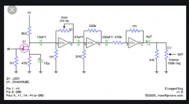
Among these better-sounding ones are the Runoff Groove "Three Legged Dog", and the Wampler Plexi-Drive.
The Three Legged Dog schematic is attached - this was designed and published on the Internet by the guys behind Runoff Groove, so I don't think there are any copyright issues in posting it here. The 'Dog uses a JFET input buffer cum gain stage, followed by two CMOS 4049 digital gates (biased to operate in linear mode) to generate the distortion. All stages are AC coupled to each other.
The Wampler Plexi-Drive is a proprietary circuit. Google will turn up some reverse-engineered schematics if you're so inclined. It uses three JFET gain stages, each one feeding the next. All stages are AC coupled.
I've seen schematics of one or two other good-sounding fuzz/distortion boxes as well. In every case, there were multiple independent distortion stages, AC coupled to each other. One very oddball one is here: 2BJTE - 2 BJT triode emulator
This "2BJTE" circuit has some obvious design flaws, but the sound-clip in the above link is worth a listen; the guitar playing itself is terrible, but the guitar tone is great!
After a lot of thinking and experimenting and simulating, I've come to the conclusion that the key to better-sounding guitar distortion is that the duty-cycle of the output waveform varies with time, from note attack to final decay.
This happens naturally in a valve guitar amp, because of the way grid current flow affects the DC bias conditions on each amplifying stage, in a way that varies with input signal amplitude.
A single op-amp diode clipper stage doesn't exhibit this effect at all - it produces mathematically precise clipping with a fixed duty-cycle though the entire guitar note, and this makes for a much more monotonous sound, at least to my ears.
The three good-sounding distortion circuits I've mentioned in this post all use "imperfect" distortion elements - JFETs, digital logic gates, BJTs. The AC coupling and imperfect nature of the devices causes DC bias voltages to shift with incoming signal strength; this in turn causes the output duty cycle to vary. And, whaddya know, these sound more like a real guitar amp, and less like the boring buzz from most distortion pedals.
-Gnobuddy
Attachments
If the input were open-circuited, that is true; but I am convinced that this is never actually the case with your pedal, because of the next thing you wrote:
This means the input jack is already wired to short the input to ground! (When nothing is plugged in, obviously.)
-Gnobuddy
The MT-2 input jack is not a shorting type. My Fender amp has many, though.
I also noticed the opamp is not multiplying the input by 3. Checking......
"In response to a strong transient, these [tube]amps exhibit what looks like 'dancing harmonics’ the spectrum analyzer. First the odds rise, and then the evens rise and fall between the odds. When a guitar is used as the signal source, the audible effect is a subtle, but musically interesting, sort of 'reedy' sound mixed with an otherwise 'brassy' sound."A single op-amp diode clipper stage doesn't exhibit this effect at all - it produces mathematically precise clipping with a fixed duty-cycle though the entire guitar note, and this makes for a much more monotonous sound, at least to my ears.
And, whaddya know, these sound more like a real guitar amp, and less like the boring buzz from most distortion pedals.
-Gnobuddy
Part of what you were talking about: "Common diodes are employed to clip first the one half of the waveform and then the other half of the waveform, but not at the same stage" John Murphy
In my first high-gain tube build, the first stage was just a gain stage with a prededing opamp buffer, followed by two stages of 1 "hot" and 1"cold" biasing. Then finally a direct-coupled CF. It sounded incredible; it possesed
"supernatural performance."
I will proffer tube distortion is not going to die soon. It's easy to roll/replace tubes and easy to modify/repair if a turret board is used along with point-to-point wiring everywhere. The MT-2 has some dynamic quality to it when compared with the MXR Dist. + depending on the settings. Update: I pulled my buff-booster out of the box and sadly found it is operating in perfect buffer mode. It was powered with a 9v battery, a 1M ground reference off the input was added, then applied a 1-1/2v positive signal from a AAA battery. The output is precisely what the battery voltage is. All the connections ping correctly with ohmmeter, and were measured from leads to wings of the opamp.
I hope I don't die on the bench.......
TL071 opamps introduce a significant amount of noise, as does the 10K input resistor.
If you want to reduce noise, both these components need to be altered. 5dB noise improvement can be expected.
If you want to reduce noise, both these components need to be altered. 5dB noise improvement can be expected.
You're forgetting that there is 8k - 18k of DC resistance inside the pickups themselves, because of the enormous length of extremely thin copper wire used to wind them.TL071 opamps introduce a significant amount of noise, as does the 10K input resistor.
If you want to reduce noise, both these components need to be altered.
As discussed many times in this thread, reality is actually much worse: the volume pot inside the e-guitar can raise the guitar's output impedance well beyond 100k, depending on where that pot is set. Most good e-guitarists will vary the pot setting as they play, to provide playing dynamics.
This is why you cannot improve perceptibly on the noise performance of a TL072 when you're dealing with an electric-guitar input stage. As I showed in a previous post, the "noisy" 18 nV/root Hz of a TL072 translates to about a 1 dB noise figure when the guitar volume control is set to half-resistance. You can't improve perceptibly on that.
You can, of course, spend extra money buying more expensive op-amps with specifications that look better on paper. They won't translate to better noise performance in this particular application, though.
-Gnobuddy
Hmm. What happens if you plug a completely un-wired 1/4 mono plug into the input of the MT-2, then? This will guarantee an open-circuit input...(and, I think, enough hiss to raise the roof.)The MT-2 input jack is not a shorting type.
I should look back at the schematic - I remember there was a cloud of JFETs clustered around the input op-amp like hornets around the picnic birthday-cake. Perhaps one of the JFETs is set to mute the MT-2's output signal when nothing is plugged into the input.
I'm too tired to do that tonight, however. It's approaching midnight here. 😴
-Gnobuddy
- Home
- Live Sound
- Instruments and Amps
- Reducing Fuzz Box Noise - Boss MT-2