So given the 24v to 230v, the maths is showing a duty cycle of 89:6%, a current ripple of 1mA and the losses increasing with switching frequency.
So I also miscalculated the inductor, 47uH? No 220mH yes.. well I can use a smaller inductor and solve the additional ripple after.
If that doesn’t work the I can try half bridge and full bridge topologies. Theyre used with more power at the expense id more components.. although with less demands on them.
Amp startup and idle with no signal.

Idling ~70W of 300W 24V PSU.
Need to add +30W of heaters to that but the SMPS approach appears to have paid off.
No big mF caps. So I'll be doing some more testing.
So I save on caps.. well except the WIMA MKPs are £28 for the two and the two coil craft inductors are £36.. so I could possibly find some cheaper.
Output B+ noise?

Sample period 4-6 seconds from start up, so I'd expect a little more LF noise drop but that's looking very good, well at least from an ideal simulation perspective!
The output tubes have a 750uF LPF/reserve cap, the input tubes have a smaller LPF but there's some additional changes I want todo which should reduce noise further in the amp.
Idling ~70W of 300W 24V PSU.
Need to add +30W of heaters to that but the SMPS approach appears to have paid off.
No big mF caps. So I'll be doing some more testing.
So I save on caps.. well except the WIMA MKPs are £28 for the two and the two coil craft inductors are £36.. so I could possibly find some cheaper.
Output B+ noise?
Sample period 4-6 seconds from start up, so I'd expect a little more LF noise drop but that's looking very good, well at least from an ideal simulation perspective!
The output tubes have a 750uF LPF/reserve cap, the input tubes have a smaller LPF but there's some additional changes I want todo which should reduce noise further in the amp.
And full 'power'..


So virtually no current change or power consumption change which is good.
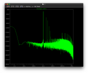
Also the noise fft - this is with a 10Khz 3.16V input and a 30Hz 3.16V input on the other channel (there's a little cross talk).
I think I can live with that.
I've already started researching/designing the PCB layout, just trying to keep the di/dt loops small but I think this will get redesigned to make the out cap loop even smaller but at the same time I don't want to cross the HV switching and LV sense/FB paths.

Annoyingly the MOSFET has a centre drain and a gate on one side - when I want to mount it on the edge of the PCB along with the diode.
So virtually no current change or power consumption change which is good.
Also the noise fft - this is with a 10Khz 3.16V input and a 30Hz 3.16V input on the other channel (there's a little cross talk).
I think I can live with that.
I've already started researching/designing the PCB layout, just trying to keep the di/dt loops small but I think this will get redesigned to make the out cap loop even smaller but at the same time I don't want to cross the HV switching and LV sense/FB paths.
Annoyingly the MOSFET has a centre drain and a gate on one side - when I want to mount it on the edge of the PCB along with the diode.
New v2 redesign on the SMPS booster and it all looks good. I've also gone through the components, located real values and updated the models for caps, inductors, etc. The model's switching is now currently running at 57KHz.
The max I've got out of the boost so far at 14A input - is 1.2A at 270V.. but that had a £37 mosfet running on it. The limit is the current through the inductors - so additional inductions would be needed however at that current we'd end up needing to look at the PCB and busbars.
So I'm happy with the performance, I'll limit it to 13A max, which works perfectly for the 230-250V with 600mA.
So my attention is starting to turn back to the amp itself, in terms of the model and finalising with the components I'd previously found or replacing with better/more suited ones.
I've also switched the 2200uF cap to Nichicon Muse ES which is bipolar (although only 50V - if the cathode is 50V then something is really wrong and the fuse should blow). Keeping the ESR and therefore the impedance as low as possible, instead of using a 2200uF I'm using 6x330uF in parallel. The result is that the ESR drops from 0.48ohm to 0.08ohm.
Next up is some adjustments on the B+ rails. They're current configured to use Nichicon 450V 300uF and 750uF but I can't find the matching configuration (I didn't note the model number). So I've started looking for some lower ESR (my thinking here is ESR is a bit like the accelerator vs the ripple which is the top speed), dynamics is a goal.
I know that "audio" caps are meant to have different internal builds but for now - I'm happy getting the thing running. I can then replace caps as I go. I know that Elina are considered very dynamic vs Panasonic/nichicon.. but I think there will be bigger issues to solve first.
The SMPS itself has a 20uF and 80uF PP 6mOhm caps that are required and seem a better investment at this time.
Current SMPS Boost model:

The boot time with the full amp is very quick and the Rsense allows the current inrush to be limited too as a bonus.
It's also a good point to get to, given work is likely to slow a little over summer.
The max I've got out of the boost so far at 14A input - is 1.2A at 270V.. but that had a £37 mosfet running on it. The limit is the current through the inductors - so additional inductions would be needed however at that current we'd end up needing to look at the PCB and busbars.
So I'm happy with the performance, I'll limit it to 13A max, which works perfectly for the 230-250V with 600mA.
So my attention is starting to turn back to the amp itself, in terms of the model and finalising with the components I'd previously found or replacing with better/more suited ones.
I've also switched the 2200uF cap to Nichicon Muse ES which is bipolar (although only 50V - if the cathode is 50V then something is really wrong and the fuse should blow). Keeping the ESR and therefore the impedance as low as possible, instead of using a 2200uF I'm using 6x330uF in parallel. The result is that the ESR drops from 0.48ohm to 0.08ohm.
Next up is some adjustments on the B+ rails. They're current configured to use Nichicon 450V 300uF and 750uF but I can't find the matching configuration (I didn't note the model number). So I've started looking for some lower ESR (my thinking here is ESR is a bit like the accelerator vs the ripple which is the top speed), dynamics is a goal.
I know that "audio" caps are meant to have different internal builds but for now - I'm happy getting the thing running. I can then replace caps as I go. I know that Elina are considered very dynamic vs Panasonic/nichicon.. but I think there will be bigger issues to solve first.
The SMPS itself has a 20uF and 80uF PP 6mOhm caps that are required and seem a better investment at this time.
Current SMPS Boost model:
The boot time with the full amp is very quick and the Rsense allows the current inrush to be limited too as a bonus.
It's also a good point to get to, given work is likely to slow a little over summer.
Last edited:
So I have my SMPS booster modelled with the large signal test, ignoring the fact that the amp needs some tuning to reduce the harmonic content, the SMPS+3080-based regulator givens sub 1mV ripple. I've tweaked the booster with a little snubbing, increased to 75KHz, added two more low ESR caps at the source as they were starting to get maxed in ripple current, added 4x20uF caps after the diode to take the current faster then added a slightly tweaked maida-christen LT3080 based regulator - currently limited to 500mA. Also the model now has 150mVpp ripple added into the initial source 24V.
This is 10Khz + 30Hz at 3.16V input. The model FFT shows 5.0 seconds to 12 seconds of simulation time (so far it's taken two nights and a day).


Note the lack of background noise
The model looks like this:

This is 10Khz + 30Hz at 3.16V input. The model FFT shows 5.0 seconds to 12 seconds of simulation time (so far it's taken two nights and a day).
Note the lack of background noise
The model looks like this:
Last edited:
Now the boost power supply is in fine tuning.. it's about time to revisit the amp and start fine tuning that too..
This is a channel, and it's looking at tad more complex than the previous post..

Each tube transconductance will differ so making each output tube adjustable becomes necessary. I've also retuned a little for 200V B+ - this may mean I need a regulator per channel to act as noise barrier, but for now this will do.
So each tube has it's own output cap bank, feedback and CCS. As each tube needs some adjustment this helps prevent it becomes a web of parallel adjustments only for temperature and ageing to compound things further.
I've explored using a CCS per channel, the this work nicely, but I've also tried making this 'stiffer' (essentially making it a more stringent regulator) however this reduces impedance and so the valve pulls the current from the CCS in preference to pulling from the output cap bank, reducing the effectiveness.
I'm now starting to look at the THD. 1V input at 1Khz:
Hmm 1.9% THD.. can do better. I suspect this is close enough for a simulation but I may adjust the operating point a little to get to 1%. I did leave the 1mV PSU ripple in but I doubt that would cause a difference..
This is a channel, and it's looking at tad more complex than the previous post..
Each tube transconductance will differ so making each output tube adjustable becomes necessary. I've also retuned a little for 200V B+ - this may mean I need a regulator per channel to act as noise barrier, but for now this will do.
So each tube has it's own output cap bank, feedback and CCS. As each tube needs some adjustment this helps prevent it becomes a web of parallel adjustments only for temperature and ageing to compound things further.
I've explored using a CCS per channel, the this work nicely, but I've also tried making this 'stiffer' (essentially making it a more stringent regulator) however this reduces impedance and so the valve pulls the current from the CCS in preference to pulling from the output cap bank, reducing the effectiveness.
I'm now starting to look at the THD. 1V input at 1Khz:
Code:
Fourier components of V(output-left)
DC component:2.23821e-07

Harmonic	Frequency	 Fourier 	Normalized	 Phase  	Normalized
 Number 	  [Hz]   	Component	 Component	[degree]	Phase [deg]
    1   	 1.000e+3	 1.094e+0	 1.000e+0	    0.04°	    0.00°
    2   	 2.000e+3	 2.073e-2	 1.895e-2	  -89.99°	  -90.02°
    3   	 3.000e+3	 4.223e-4	 3.860e-4	    0.11°	    0.07°
    4   	 4.000e+3	 2.381e-5	 2.176e-5	   90.25°	   90.21°
    5   	 5.000e+3	 2.270e-6	 2.075e-6	 -179.63°	 -179.66°
    6   	 6.000e+3	 2.801e-7	 2.561e-7	  -90.03°	  -90.07°
    7   	 7.000e+3	 3.936e-8	 3.598e-8	    0.38°	    0.34°
    8   	 8.000e+3	 9.387e-9	 8.581e-9	  103.14°	  103.10°
    9   	 9.000e+3	 8.857e-10	 8.096e-10	  120.05°	  120.01°
Total Harmonic Distortion: 1.895205%(1.895206%)
Hmm 1.9% THD.. can do better. I suspect this is close enough for a simulation but I may adjust the operating point a little to get to 1%. I did leave the 1mV PSU ripple in but I doubt that would cause a difference..
Last edited:
Front end output I see this
Code:
Direct Newton iteration for .op point succeeded.
N-Period=1
Fourier components of V(l-out-grid-start)
DC component:6.3806

Harmonic	Frequency	 Fourier 	Normalized	 Phase  	Normalized
 Number 	  [Hz]   	Component	 Component	[degree]	Phase [deg]
    1   	 1.000e+3	 2.339e+0	 1.000e+0	   -0.01°	    0.00°
    2   	 2.000e+3	 1.893e-2	 8.093e-3	  -90.06°	  -90.05°
    3   	 3.000e+3	 8.430e-5	 3.604e-5	  179.67°	  179.68°
    4   	 4.000e+3	 3.402e-5	 1.454e-5	  -90.25°	  -90.24°
    5   	 5.000e+3	 4.635e-6	 1.982e-6	   -0.38°	   -0.37°
    6   	 6.000e+3	 6.208e-7	 2.654e-7	   89.26°	   89.27°
    7   	 7.000e+3	 1.067e-7	 4.561e-8	 -179.66°	 -179.65°
    8   	 8.000e+3	 6.734e-9	 2.879e-9	 -151.86°	 -151.85°
    9   	 9.000e+3	 2.148e-8	 9.184e-9	  -22.21°	  -22.20°
Total Harmonic Distortion: 0.809335%(0.809335%)
Code:
Fourier components of V(output-left)
DC component:-8.41261e-06

Harmonic	Frequency	 Fourier 	Normalized	 Phase  	Normalized
 Number 	  [Hz]   	Component	 Component	[degree]	Phase [deg]
    1   	 1.000e+3	 4.735e-1	 1.000e+0	    0.09°	    0.00°
    2   	 2.000e+3	 1.238e-2	 2.615e-2	  -89.95°	  -90.03°
    3   	 3.000e+3	 1.576e-5	 3.329e-5	  175.58°	  175.49°
    4   	 4.000e+3	 1.984e-5	 4.190e-5	   90.27°	   90.18°
    5   	 5.000e+3	 7.441e-7	 1.571e-6	 -178.81°	 -178.89°
    6   	 6.000e+3	 1.570e-7	 3.315e-7	  -91.52°	  -91.61°
    7   	 7.000e+3	 1.796e-8	 3.792e-8	   -2.03°	   -2.12°
    8   	 8.000e+3	 8.152e-9	 1.722e-8	  149.38°	  149.29°
    9   	 9.000e+3	 6.971e-10	 1.472e-9	  152.51°	  152.42°
Total Harmonic Distortion: 2.615248%(2.615248%)
So this has a larger second harmonic that the original setup, but the the 3rd is lower.

Only thing is this produces less output, however shows you can adjust the harmonics. For now the original settings are probably the best starting point.
Last edited:
The ECC99 load lines as they are currently showing the near vertical low impedance line - anode/cathode it doesn't matter they're both steep:

If you look at the left, that bend in the 150V line is what's giving us some of that loving THD..
So first up - I'm looking to tune the output section without NFB running.. lowing the voltage to 135V but keeping the same current operating point.
If you look at the left, that bend in the 150V line is what's giving us some of that loving THD..
So first up - I'm looking to tune the output section without NFB running.. lowing the voltage to 135V but keeping the same current operating point.
Last edited:
At 55ohms that's Total Harmonic Distortion: 1.828005%(1.828005%) external 180deg feedback from the output itself.
2 2.000e+3 2.033e-2 1.827e-2 -89.98° -90.02°
3 3.000e+3 5.210e-4 4.684e-4 0.12° 0.08°
4 4.000e+3 3.907e-5 3.512e-5 90.28° 90.24°
This rises using the internal original feedback, 1.912218%(1.912218%), however I'm also aware that ltspice has some variation in terms each run.
2 2.000e+3 2.182e-2 1.912e-2 -89.96° -90.02°
3 3.000e+3 5.702e-4 4.996e-4 0.18° 0.13°
4 4.000e+3 4.789e-5 4.196e-5 90.36° 90.31°
I think there's obviously some tuning that can be done of the feedback too and I could bang my head against a brick wall resulting in paralysis by analysis.
So for my first build I think this will do. I can tune it once the hardware is running in front of me.
I am having a quick shifty (look) at the front end 12BH7A tuning. It's occurred to me that putting a heap of voltage gain into a ecc99 output wouldn't help that much, the THD and in general the distortions, would rise too high given the output we're after.
As a basic design there's not much you can do (other than play with feedback). I can see why people for OTL use either masses of tubes to plumb for PP configuration/fets for low impedance. I think if I need more oophm I would put a couple of fet followers.
DC component:-162.89
Harmonic Frequency Fourier Normalized Phase Normalized
Number [Hz] Component Component [degree] Phase [deg]
1 1.000e+3 1.994e+0 1.000e+0 -6.82° 0.00°
2 2.000e+3 2.443e-2 1.225e-2 -100.42° -93.60°
3 3.000e+3 2.715e-4 1.361e-4 -34.66° -27.84°
4 4.000e+3 7.735e-6 3.878e-6 67.89° 74.70°
5 5.000e+3 1.168e-7 5.858e-8 141.32° 148.14°
6 6.000e+3 1.705e-7 8.549e-8 -120.25° -113.43°
7 7.000e+3 1.483e-7 7.437e-8 70.60° 77.41°
8 8.000e+3 4.105e-7 2.058e-7 165.46° 172.28°
9 9.000e+3 2.254e-7 1.130e-7 -64.21° -57.40°
Total Harmonic Distortion: 1.225063%(1.225063%)
I know some of the geeks will notice something.
Inverse Flutterman without feedback, first run, using a a LTP differential amp with the 12BH7As and paralleled flutter man PP section - 2x.
Tonally very different given the 3rd order harmonic "increase". In reality it compared to before it appears the cancellation of the other harmonics just reveals the 3rd more.


Made the same mistake that others have made on the futterman.. accidentally grounded the feedback into the phase splitter.
Just going to see what the outcome in THD if this run will be, an early FFT of the output, however you'll note the little output drop of the fundamental:

Promising, and needing a little more tuning..
Just going to see what the outcome in THD if this run will be, an early FFT of the output, however you'll note the little output drop of the fundamental:
Promising, and needing a little more tuning..
Last edited:
Code:
Fourier components of V(output-left)
DC component:3.93979e-07

Harmonic	Frequency	 Fourier 	Normalized	 Phase  	Normalized
 Number 	  [Hz]   	Component	 Component	[degree]	Phase [deg]
    1   	 1.000e+3	 4.857e-1	 1.000e+0	   -6.87°	    0.00°
    2   	 2.000e+3	 9.936e-3	 2.046e-2	 -104.19°	  -97.32°
    3   	 3.000e+3	 4.019e-5	 8.276e-5	  -47.32°	  -40.45°
    4   	 4.000e+3	 4.290e-6	 8.834e-6	   65.12°	   71.99°
    5   	 5.000e+3	 1.098e-7	 2.260e-7	  159.65°	  166.52°
    6   	 6.000e+3	 1.568e-8	 3.229e-8	 -131.72°	 -124.85°
    7   	 7.000e+3	 1.733e-9	 3.569e-9	  -27.88°	  -21.01°
    8   	 8.000e+3	 1.956e-9	 4.027e-9	  123.11°	  129.98°
    9   	 9.000e+3	 1.513e-10	 3.115e-10	 -136.68°	 -129.81°
Total Harmonic Distortion: 2.045861%(2.045861%)
Now I worked out what is the issue - I suspect that the LTP version of this may reduce the harmonics too. Also need to add the global feedback output-to-input in too.
Last edited:
Needs a little more - this is an LTP based phase splitter..
DC component:0.000391201
Harmonic Frequency Fourier Normalized Phase Normalized
Number [Hz] Component Component [degree] Phase [deg]
1 1.000e+3 4.110e-1 1.000e+0 -3.52° 0.00°
2 2.000e+3 3.791e-3 9.222e-3 55.44° 58.96°
3 3.000e+3 3.510e-4 8.539e-4 -18.03° -14.50°
4 4.000e+3 4.299e-6 1.046e-5 -91.65° -88.13°
5 5.000e+3 1.256e-7 3.057e-7 169.67° 173.19°
6 6.000e+3 1.580e-9 3.844e-9 125.77° 129.30°
7 7.000e+3 3.514e-10 8.548e-10 -146.94° -143.42°
8 8.000e+3 4.692e-10 1.141e-9 1.34° 4.86°
9 9.000e+3 1.767e-10 4.299e-10 -8.33° -4.81°
Total Harmonic Distortion: 0.926183%(0.926183%)
Attachments
Last edited:
This weekend's task.. figure out where the pesky harmonics are creeping in from this run:

LTP-based futterman.
I suspect a little TLC is needed in front end tuning.
LTP-based futterman.
I suspect a little TLC is needed in front end tuning.
Fourier components of V(output-left)
DC component:0.000303191
Harmonic Frequency Fourier Normalized Phase Normalized
Number [Hz] Component Component [degree] Phase [deg]
1 1.000e+3 2.048e+0 1.000e+0 5.69° 0.00°
2 2.000e+3 5.365e-2 2.620e-2 -81.33° -87.03°
3 3.000e+3 9.620e-3 4.697e-3 4.84° -0.85°
4 4.000e+3 8.000e-4 3.906e-4 -102.25° -107.94°
5 5.000e+3 9.588e-4 4.682e-4 -4.33° -10.03°
6 6.000e+3 3.298e-4 1.610e-4 -99.95° -105.64°
7 7.000e+3 2.665e-4 1.301e-4 -7.05° -12.74°
8 8.000e+3 1.730e-4 8.446e-5 -101.65° -107.34°
9 9.000e+3 9.299e-5 4.541e-5 -9.17° -14.86°
Total Harmonic Distortion: 2.662130%(2.662138%)
Hmm output from a Atmasphere M60 inspired front end - on the upper grid of the PP stage:
Hmm...
Output doesn't look that bad.. I still need to tube the PP next.

Code:
DC component:3.77439

Harmonic	Frequency	 Fourier 	Normalized	 Phase  	Normalized
 Number 	  [Hz]   	Component	 Component	[degree]	Phase [deg]
    1   	 1.000e+3	 1.627e+0	 1.000e+0	  163.20°	    0.00°
    2   	 2.000e+3	 4.372e-2	 2.687e-2	    3.07°	 -160.13°
    3   	 3.000e+3	 6.094e-3	 3.745e-3	  173.85°	   10.65°
    4   	 4.000e+3	 3.029e-4	 1.861e-4	   42.22°	 -120.98°
    5   	 5.000e+3	 2.229e-5	 1.370e-5	 -115.49°	 -278.69°
    6   	 6.000e+3	 1.897e-6	 1.165e-6	  114.77°	  -48.43°
    7   	 7.000e+3	 1.477e-7	 9.078e-8	  -21.57°	 -184.77°
    8   	 8.000e+3	 1.269e-8	 7.795e-9	 -166.18°	 -329.38°
    9   	 9.000e+3	 1.533e-8	 9.418e-9	  -71.99°	 -235.19°
Total Harmonic Distortion: 2.712761%(2.712761%)
Hmm...
Output doesn't look that bad.. I still need to tube the PP next.
No feedback M60-inspired PP OTL:

So I've been investigating distortion and there's a number of ways to counter this, all trade offs but interesting - some my understand at the moment (and some of this may be wrong):
1. PP vs 'SE' - there's naturally a cancellation effect, specifically from the power supply where the +ve and -ve cancel the same noise on both channels. How much harmonics are cancelled from the incoming signal? that depends as the harmonic signature appears on both anode and cathode. The PP section itself has a cancellation effect of it's own H2 harmonics, however with PP and zero crossover distortion we add odd harmonics.
2. High voltage vs low voltage - this is an interesting one. When you look at your load calculators, they would show rising THD but on closer inspection that harmonic content is often higher even than odd, thus sacrificing to reduce odd distortion means more even - however that can be a moot point if you're system is in the mucky area of the load graph.
3. Voltage vs Current. It seems the more current, the more distortion in relative comparison with voltage based systems. This works against OTLs output stages.
4. Even harmonics through the cathode can produce odd harmonics. This can be signal but can also be power noise.
5. Stages can be used to reduce harmonics by cancelling the harmonics of the previous stage. For example: signal -> 12bh7 output via anode -> grid of the next stage 12bh7 inverts the input harmonics, so with the correct load resistances you can consecutively cancel out harmonics from the previous stages. I would expect that you could even go to the point of selecting a particular tube for this effect or design to cancel out the bad harmonics characteristics of a tube.
6. Power noise - this comes down to the ripple/rectification. Using B- lines Vripple allows you to add cancellation. This is also a safety thing - to ensure any large power ripple is cancelled rather than create a high volume sound.
I'm still progressing with the design, I will probably for the simplist single ended for the first iteration, but I have some ideas from this exploration I'll drop into that design.
The issue with PP is the negative rail, and for that boost converters don't work - they share the same ground line as the source supply and as such I can't even create a ground mid way in a boosted 400Vdc supply for example.
Fourier components of V(output-left)
DC component:-9.34797e-05
Harmonic Frequency Fourier Normalized Phase Normalized
Number [Hz] Component Component [degree] Phase [deg]
1 1.000e+3 8.120e-1 1.000e+0 156.81° 0.00°
2 2.000e+3 1.255e-2 1.545e-2 -14.69° -171.50°
3 3.000e+3 2.015e-3 2.481e-3 139.31° -17.50°
4 4.000e+3 3.552e-5 4.374e-5 -12.01° -168.82°
5 5.000e+3 1.836e-6 2.261e-6 108.42° -48.39°
6 6.000e+3 9.671e-8 1.191e-7 -118.66° -275.47°
7 7.000e+3 5.412e-9 6.665e-9 28.88° -127.94°
8 8.000e+3 5.563e-10 6.851e-10 121.02° -35.79°
9 9.000e+3 1.153e-10 1.420e-10 108.41° -48.40°
Total Harmonic Distortion: 1.565032%(1.565032%)
So I've been investigating distortion and there's a number of ways to counter this, all trade offs but interesting - some my understand at the moment (and some of this may be wrong):
1. PP vs 'SE' - there's naturally a cancellation effect, specifically from the power supply where the +ve and -ve cancel the same noise on both channels. How much harmonics are cancelled from the incoming signal? that depends as the harmonic signature appears on both anode and cathode. The PP section itself has a cancellation effect of it's own H2 harmonics, however with PP and zero crossover distortion we add odd harmonics.
2. High voltage vs low voltage - this is an interesting one. When you look at your load calculators, they would show rising THD but on closer inspection that harmonic content is often higher even than odd, thus sacrificing to reduce odd distortion means more even - however that can be a moot point if you're system is in the mucky area of the load graph.
3. Voltage vs Current. It seems the more current, the more distortion in relative comparison with voltage based systems. This works against OTLs output stages.
4. Even harmonics through the cathode can produce odd harmonics. This can be signal but can also be power noise.
5. Stages can be used to reduce harmonics by cancelling the harmonics of the previous stage. For example: signal -> 12bh7 output via anode -> grid of the next stage 12bh7 inverts the input harmonics, so with the correct load resistances you can consecutively cancel out harmonics from the previous stages. I would expect that you could even go to the point of selecting a particular tube for this effect or design to cancel out the bad harmonics characteristics of a tube.
6. Power noise - this comes down to the ripple/rectification. Using B- lines Vripple allows you to add cancellation. This is also a safety thing - to ensure any large power ripple is cancelled rather than create a high volume sound.
I'm still progressing with the design, I will probably for the simplist single ended for the first iteration, but I have some ideas from this exploration I'll drop into that design.
The issue with PP is the negative rail, and for that boost converters don't work - they share the same ground line as the source supply and as such I can't even create a ground mid way in a boosted 400Vdc supply for example.
Just in contrast adding some PP feedback into the driver stage:
So there's still some optimisation I think. I'd like to explore the concepts/ideas using ltspice (the reality will be different I know) in terms of reducing harmonics and noise.
Code:
Harmonic	Frequency	 Fourier 	Normalized	 Phase  	Normalized
 Number 	  [Hz]   	Component	 Component	[degree]	Phase [deg]
    1   	 1.000e+3	 7.900e-1	 1.000e+0	  157.11°	    0.00°
    2   	 2.000e+3	 1.073e-2	 1.358e-2	   -2.55°	 -159.66°
    3   	 3.000e+3	 1.975e-3	 2.500e-3	  138.73°	  -18.37°
    4   	 4.000e+3	 3.185e-5	 4.032e-5	   37.63°	 -119.48°
Total Harmonic Distortion: 1.380393%(1.380393%)
So there's still some optimisation I think. I'd like to explore the concepts/ideas using ltspice (the reality will be different I know) in terms of reducing harmonics and noise.
So more experimentation with the modelling.
NFB stealing some output, so there's a more tuning needed there but this change? Two 12BH7A acting as a CCS for the input section.
I could add a CCS on the next stage too... however it's interesting in seeing the impact that such a change makes. There are now four 12BH7A-STR tubes on each channel frontend with 4 ecc99 on the backend for each channel.
Personally I would prefer to change the backend PP to something more effective..
I'm also very interested in the discussions going on around tube based smps and tube class-D which seem just up my street.. perhaps I should rename this amp Le Compliqué.
DC component:0.00771776
Harmonic Frequency Fourier Normalized Phase Normalized
Number [Hz] Component Component [degree] Phase [deg]
1 1.000e+3 4.104e-1 1.000e+0 155.77° 0.00°
2 2.000e+3 3.593e-3 8.755e-3 -77.98° -233.75°
3 3.000e+3 8.011e-4 1.952e-3 119.75° -36.02°
4 4.000e+3 1.453e-5 3.541e-5 -93.07° -248.84°
5 5.000e+3 1.032e-6 2.515e-6 171.39° 15.62°
6 6.000e+3 4.479e-8 1.091e-7 108.59° -47.18°
7 7.000e+3 8.632e-8 2.103e-7 179.70° 23.93°
8 8.000e+3 9.236e-9 2.251e-8 -155.73° -311.50°
9 9.000e+3 3.945e-9 9.612e-9 169.22° 13.45°
Total Harmonic Distortion: 0.897055%(0.897055%)
NFB stealing some output, so there's a more tuning needed there but this change? Two 12BH7A acting as a CCS for the input section.
I could add a CCS on the next stage too... however it's interesting in seeing the impact that such a change makes. There are now four 12BH7A-STR tubes on each channel frontend with 4 ecc99 on the backend for each channel.
Personally I would prefer to change the backend PP to something more effective..
I'm also very interested in the discussions going on around tube based smps and tube class-D which seem just up my street.. perhaps I should rename this amp Le Compliqué.
- Home
- Amplifiers
- Headphone Systems
- Designing my headphone amp