Average current draw for each channel is about 90mA, peaks under load are higher.
As this is a constant draw you want to double that at least so your transformer/wallwart or similar doesn´t get too hot.
So yes, 12V/1A is fine.
Should be well regulated though.
As this is a constant draw you want to double that at least so your transformer/wallwart or similar doesn´t get too hot.
So yes, 12V/1A is fine.
Should be well regulated though.

discharge resistor necessary?
According to DC offset with output coupling capacitors ,specifically post #5, a discharge resistor at the output is advisable. Is there a reason for not using it in this circuit?
According to DC offset with output coupling capacitors ,specifically post #5, a discharge resistor at the output is advisable. Is there a reason for not using it in this circuit?
Ordered a prototype batch (5) from JLCPCB so if anybody is interested,
I can let go up to 3 PCBs for 2.50$/pc. plus shipping.
I am up for one please.
Hi, I would like to get one as well. BR, ErnstOrdered a prototype batch (5) from JLCPCB so if anybody is interested,
I can let go up to 3 PCBs for 2.50$/pc. plus shipping.
Totally forgot the most important part:
Lineup, do you want the 1st PCB?
It would be free of charge of course.
Otherwise I hope you'll get to read happy reviews at least!
Lineup, do you want the 1st PCB?
It would be free of charge of course.
Otherwise I hope you'll get to read happy reviews at least!
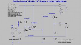
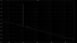
how about transconductance?
yes, a waste in output power and higher output impedance, but still interesting. Lower THD and nice harmonics profile.
yes, a waste in output power and higher output impedance, but still interesting. Lower THD and nice harmonics profile.
Attachments

Last edited:
Don´t worry lohk, I reserved a PCB for you.
Will send it friday at the latest.
Mine is already up and running.
12V Meanwell SMPS and 2x RC-filter (2.2Ohm) and thus 11.2V at the amp.
(skipped the regulator)
Used BC327/337; that´s what I had.
Despite builders bias the amp has been running since friday
and is easily the best of amps I can compare it to right now.
(Porta 3move from Meier Audio; OPA627+BUF634; Sapphire)
It is so quiet with the SMPS/RC-filter that I often think it´s not switched on.
The bass extension and control with my Sennheiser HD598 is very good; meaning it is as it should be not overblown.
The most remarkable quality though is the mid+treble region.
It has a three-dimensionality to the sound that I never had with other amps.
I like to think that all these opamp and complex circuit have hidden this somewhat!? Don´t know!
All I know that I am in love with this amp for now.
I will upgrade my DAC too; already ordered a Topping E30 to go with it.
Thank you lineup!
Another layout
Just thought it was time to share another version of this pretty cool amp.
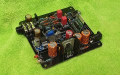
I used the same schematic as my previous layout but with the correct input filtering this time and a full 100x100 board.
And with all that extra space, I added an option for a bluetooth module that is run from a buck converter.
Without the BT module plugged in, the amp is silent and sounds as good as my last layout. There is 30mV 150KHz noise on the VCC rail from the buck converter, but this is inaudible. This is because I took a feed off the 12v regulated line rather than asking the buck converter to drop 19v to 5v. A simple toggle switch to kill the power to the buck converter (I could label it 'HQ mode' 😀 ) will take care of that noise when not on BT source. The layout is flexible enough that I could also cut the 12v feed and run a jumper from the DC barrel socket to the buck converter instead and see how it performs with the heat.
The BT module is another matter though. They are notoriously noisy. I used the manufacturer's recommended schematic but the module beeps and screams and carries on. It is sending so much junk back through the ground that the LM317 is unstable.
However, I have tried with the BT module fed by an independent power supply and it works perfectly. I am waiting on a shipment of B0505S-1W DC-DC isolators so I can hopefully bootstrap a solution.
I also need to add some volume reduction to the BT module, because the initial connection announcements are made at full volume..into almost 4x gain.. I learned quickly to not have headphones on whilst powering up!
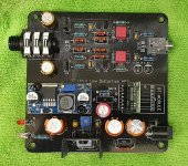
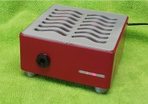
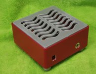
I 3D printed a case for this one as a prototype and it came out pretty good..except for a power outage at 99% completion (20 something hours in) 🙄 This accounts for the unfinished look at the top.
I'll run a set of measurements on the amp later.
Anyway, enough words, here are the pictures:


Just thought it was time to share another version of this pretty cool amp.
I used the same schematic as my previous layout but with the correct input filtering this time and a full 100x100 board.
And with all that extra space, I added an option for a bluetooth module that is run from a buck converter.
Without the BT module plugged in, the amp is silent and sounds as good as my last layout. There is 30mV 150KHz noise on the VCC rail from the buck converter, but this is inaudible. This is because I took a feed off the 12v regulated line rather than asking the buck converter to drop 19v to 5v. A simple toggle switch to kill the power to the buck converter (I could label it 'HQ mode' 😀 ) will take care of that noise when not on BT source. The layout is flexible enough that I could also cut the 12v feed and run a jumper from the DC barrel socket to the buck converter instead and see how it performs with the heat.
The BT module is another matter though. They are notoriously noisy. I used the manufacturer's recommended schematic but the module beeps and screams and carries on. It is sending so much junk back through the ground that the LM317 is unstable.
However, I have tried with the BT module fed by an independent power supply and it works perfectly. I am waiting on a shipment of B0505S-1W DC-DC isolators so I can hopefully bootstrap a solution.
I also need to add some volume reduction to the BT module, because the initial connection announcements are made at full volume..into almost 4x gain.. I learned quickly to not have headphones on whilst powering up!
I 3D printed a case for this one as a prototype and it came out pretty good..except for a power outage at 99% completion (20 something hours in) 🙄 This accounts for the unfinished look at the top.
I'll run a set of measurements on the amp later.
Anyway, enough words, here are the pictures:
Attachments
Last edited:

Nice layout avtech23!
Pretty brave to include a switcher and bluetooth!
But I´m sure you will work it out.
I see you run the main transistors without heatsink.
I added a aluminium strip to mine and the PCB still gets pretty warm.
And a super-cute little case that is!
I could see this in the diyaudio-store or so.
Pretty brave to include a switcher and bluetooth!
But I´m sure you will work it out.
I see you run the main transistors without heatsink.
I added a aluminium strip to mine and the PCB still gets pretty warm.
And a super-cute little case that is!
I could see this in the diyaudio-store or so.
Haha I did wonder 😀
Thanks Joens, once I get the case design ironed out I'll drop some .STL and gerber files for anyone interested. A little bit of CAD work left to do though, but I'm happy with how this one is progressing.
I have some little TO220 heatsinks from AVID on order for the BD139s, so I'll add those later. My last versions are running without anything and I am only getting ~65 degrees celcius on the tabs (from memory), which was within the SOAR specs. An (insulated) aluminium strip across would definitely help with heat distribution and dissipation for sure.
Maybe brave, but I had the empty space on the board so I figured I'd go all out and try to make a more flexible board this time as I don't always want the extra wires when travelling. The switcher and BT module can be left unpopulated and it won't hurt a thing. Once I get things dialled in, I'll take some measurements with and without the switcher and BT and see what the cost is in terms of sound quality. It will be interesting to find out.
Glad to see you have yours up and running and enjoying it too!
Cheers
Nice layout avtech23!
Pretty brave to include a switcher and bluetooth!
But I´m sure you will work it out.
I see you run the main transistors without heatsink.
I added a aluminium strip to mine and the PCB still gets pretty warm.
And a super-cute little case that is!
I could see this in the diyaudio-store or so.
Thanks Joens, once I get the case design ironed out I'll drop some .STL and gerber files for anyone interested. A little bit of CAD work left to do though, but I'm happy with how this one is progressing.
I have some little TO220 heatsinks from AVID on order for the BD139s, so I'll add those later. My last versions are running without anything and I am only getting ~65 degrees celcius on the tabs (from memory), which was within the SOAR specs. An (insulated) aluminium strip across would definitely help with heat distribution and dissipation for sure.
Maybe brave, but I had the empty space on the board so I figured I'd go all out and try to make a more flexible board this time as I don't always want the extra wires when travelling. The switcher and BT module can be left unpopulated and it won't hurt a thing. Once I get things dialled in, I'll take some measurements with and without the switcher and BT and see what the cost is in terms of sound quality. It will be interesting to find out.
Glad to see you have yours up and running and enjoying it too!
Cheers

Went through this thread a 3rd time today and now I'm actually seriously tempted to try and make a board for this. It looks like a really nice amp and will compliment my planned push/pull amp very nicely 😀
This thread might have the highest quotient (PCB-designs/posts) which makes for a good SNR! Just like the amp.
And yes, it should be fine. The electrolyts probably dry out sooner from that little heat there is.
Sounds about right. I believe the Rth_ja=100K/W and at Pd~0.35W, you´d expect 35K rise in temperature.My last versions are running without anything and I am only getting ~65 degrees celcius on the tabs (from memory), which was within the SOAR specs.
And yes, it should be fine. The electrolyts probably dry out sooner from that little heat there is.
I am a little confused here. You have the linear regulator for 12V.This is because I took a feed off the 12v regulated line rather than asking the buck converter to drop 19v to 5v.
The buck-converter is fed by that and converts to 5V, correct?
Why don´t you use the buck@19V, that´s more efficient and you don´t dirty the amps 12V-line. Maybe you can lift a leg somewhere and try a wire directly to the 19V input.
That way the LM317 is maybe happier.
Other than that, I could only think of simply trying to introduce some inductance in the supply lines between BT&buck and/or buck&12V so the ripple is attenuated before it gets back to the 12V-line.
I was thinking that dropping 19v to 5v would generate lots of heat, but i had traditional regulators stuck in my head at the time and why I wired it to the 12v line. There is only 60mA being drawn from the buck converter so I needn't have worried.
The handy thing is that the buck converter is mounted on standoffs and then connected down to the board, which means it is easy to cut that connection and run a wire direct to the DC in and get the 19v feed.
I hand wound an inductor for between the BT and Buck whilst waiting for a 10mH to arrive. I managed to achieve 1.5mH which helped but nowhere near enough to filter the noise. Once the 10mH arrives, I'll try that and use the 19v feed and go from there.
- Home
- Amplifiers
- Headphone Systems
- 3 Transistor HP Amplifier with low dist