Scott, you should more carefully check the data sheets, before challenging me. MY Toshiba handbook shows at 4ma: 28,000 for the 2SK170, and 29,000 for the 2SJ74. It is the CAPACITANCE that is so different.
Manufacturing tolerances are probably 5-10%, as I've said before there are no commercial FET's to fake these with, re-brands are way off on Vp, Idss, and Yfs and are just a take the money and run scam. The Yfs vs Id plot is all that matters I have never seen a single other FET that come close. Promoting the sorting of FET's by Idss only helps those selling fakes, they take high Idss switches from someone like Fairchild which have large Vp's and the Yfs is way off but no one notices.
Last edited:
...
Zung, you probably have fake jfets, the n and p Toshiba devices should be almost exactly the same for Gm. Yours differ. (for example)
Not quite if you look at the datasheets.
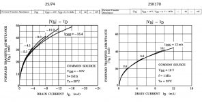
The devil is in the detail (and the scale).
I did a little montage here for your enjoyments: you can see the advertized ("typical") Yfs is the same, but if you look at the Yfs vs Id curves, with Idss=12mA, the J74 is slightly ahead at about 47mS, while the K170 is a bit behind at about 44mS. I'd call it 5-10% diff. In my batch of 50, I have an average of 38mS for the J, and 33mS for the K for about 15% diff.
Btw, I was expecting mines to be fakes; I just wanted to know how fake they can be, and I'm satisfied with the results. For a definitive answer, I guess I'll have to build something to measure the noise. Maybe someday.
Attachments
Actually, Zung, I probably need to stand corrected. Your devices are close enough to be real Toshiba.
Since Toshiba has phased out the audio jFET a long time ago. The Linear System ones are too expensive for e-bay seller to use. Does that mean that the fake K170/J74 are reasonably good this day?Actually, Zung, I probably need to stand corrected. Your devices are close enough to be real Toshiba.
Last edited:
They look pretty good if you change your plots to the same coordinate scales.The devil is in the detail (and the scale).
I did a little montage here for your enjoyments: you can see the advertized ("typical") Yfs is the same, but if you look at the Yfs vs Id curves, with Idss=12mA, the J74 is slightly ahead at about 47mS, while the K170 is a bit behind at about 44mS. I'd call it 5-10% diff. In my batch of 50, I have an average of 38mS for the J, and 33mS for the K for about 15% diff.
Btw, I was expecting mines to be fakes; I just wanted to know how fake they can be, and I'm satisfied with the results. For a definitive answer, I guess I'll have to build something to measure the noise. Maybe someday.
Does that mean that the fake K170/J74 are reasonably good this day?
There are no fake K170/J74 just re-brands of parts to take the money and run how many times do I have to say this?
Well, they don't make them in a garage, like you think Bybees are made, but usually only a few jfets have the transconductance that the 170-74 combination have. However, my original designs worked reasonably well, so something roughly equivalent will work reasonably well too.
My experience,
actually measuring parts in real life with real test equipment,
agrees with Scott Wurcer's observations: The counterfeits measure SO MUCH DIFFERENTLY than the original Toshibas, that you only need 10% accurate measurement gear to decide. The counterfeits are more than 20%, in fact much more than 20%, different than the Toshiba parts.
Build your test jig. Calibrate it. Measure parts ---> and succeed! Congratulations.
The real problem is the differences between N and P mobility. That is the key to differences in Gm. Toshiba made a serious attempt to make the complementary parts match in Gm as closely as possible (obviously) If you had to use Siliconix parts, like I used to have to do, you would find a big difference in Gm between otherwise similar N and P channel jfets, even if their chips were of similar size. For example: the J113-J174 combination (American) that I used in the 1970's. This is why Siliconix initially recommended the J212 instead of the J113. It had a lower Gm that more closely matched the P channel jfets of the day. Unfortunately, the J212 had serious leakage problems (with higher voltage) that most other jfets did not have and it is not recommended anymore. If one looks at my old schematics of the Levinson JC-2 you will find the J212 there, but no more with future designs.
While I am on line, I might mention something else that I think is important.
I did not use an output stage (follower) deliberately when I designed the original circuit as a line driver for the GD. I did it to simplify the thru-path, increase the stability with cap load, and greatly increase the open loop bandwidth by limiting the voltage gain of the second stage with a relatively low Z load. It worked out to sound better than expected, so we used it with the JC-2 later on. However, adding a follower output stage makes it an OP-AMP, not a TRANS-AMP, and it is not necessarily as good sonically. Now sometimes it is necessary, like when you want to drive headphones (low Z), or loudspeakers, BUT less is best, so don't add the follower if you want the best sound and have a relatively high Z load to drive. Scott will not agree with me on this, so try both for yourself.
I did not use an output stage (follower) deliberately when I designed the original circuit as a line driver for the GD. I did it to simplify the thru-path, increase the stability with cap load, and greatly increase the open loop bandwidth by limiting the voltage gain of the second stage with a relatively low Z load. It worked out to sound better than expected, so we used it with the JC-2 later on. However, adding a follower output stage makes it an OP-AMP, not a TRANS-AMP, and it is not necessarily as good sonically. Now sometimes it is necessary, like when you want to drive headphones (low Z), or loudspeakers, BUT less is best, so don't add the follower if you want the best sound and have a relatively high Z load to drive. Scott will not agree with me on this, so try both for yourself.
They look pretty good if you change your plots to the same coordinate scales.
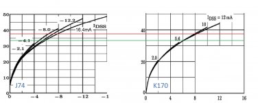
You're right. Here's a photoshopped version.
Now that gives me yet another crazy idea: if we intentionally mismatched the Idss and took, say the J74 @ -16.4 mA and the K170 @ 12 mA, and ran them at reduced Id? The matching seems pretty good in the area between the red and the green line, Id = 6 to 8 mA. Maybe that's why I noticed lower distortion while running the sim's.
Doable?
Attachments
Last edited:
Scott will not agree with me on this, so try both for yourself.
😀😀😀 I'm using a JC2 to directly drive my 300 Ohm headphones right now. The one without the followers.
Last edited:
Build your test jig. Calibrate it. Measure parts ---> and succeed! Congratulations.
This is more elaborate than most folks might do, but I did this when Linear Systems was first sampling their parts and I wanted to provide some feedback.
I took the Digilent Analog Discovery USB card and made a simple curve tracer with a few Python scripts. Taking Vgs vs Id at 100 points quickly there are no self heating issues. The data was least squares fit to the ideal JFET equation, here the plot of the data and the fit are nearly coincident. The red line is the difference here shown as current delta vs Vgs. The fit is very good, the slight "s" shape error is typical with slight deviation at the high end for high current effects and parasitic resistances, at the low end for sub-threshold effects.
I might add this is IMO a better way to extract Vp because it fits the data where you are going to use the FET not the usual way of measuring it in deep sub-threshold. Once you have Vp and Idss you can compute the gm, operating point, and matching in almost any application. A simple rearrangement of the FET equation can include a small source degeneration to cover even more applications.
Saving the data to a two column file you can use Excell to sort in any dimension you want.
Attachments

Last edited:
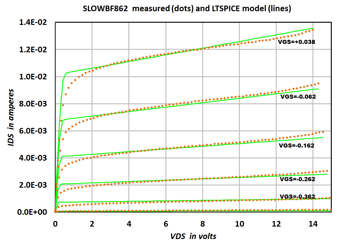
I did similar things with a "Locky-Z Intelligent Curve Tracer" and a BF862 JFET. I found that the JFET modeling equation in LTSPICE has only three parameters that matter for DC I-V curves in normal operating modes: BETA, VTO, and LAMBDA.
LAMBDA sets the slope (dIds/dVds) in the saturation region and can be fitted separately.
This leaves only VTO and BETA. They can be extracted from triplets of measured data (Vgs, Vds, Ids) using Excel, either with Trendlines or the built in optimizer. The results are pleasant:
_
_
LAMBDA sets the slope (dIds/dVds) in the saturation region and can be fitted separately.
This leaves only VTO and BETA. They can be extracted from triplets of measured data (Vgs, Vds, Ids) using Excel, either with Trendlines or the built in optimizer. The results are pleasant:
_
_
Code:
*
*
.MODEL  SLOWBF862  NJF( VTO=-5.083E-1  BETA=3.394E-2  LAMBDA=2.426E-2 IS=1.19E-13   N=1.255
+                       ISR=3P         NR=2           RS=0.5         RD=0.5         BETATCE=-0.5
+                       VTOTC=-2E-3    ALPHA=1E-3     VK=6.0E2       M=0.6          PB=0.5
+                       FC=0.5         CGS=9.5P       CGD=7.5P       KF=8.75E-17    AF=1
+                       MFG=NXP)
*
Last edited:
... BUT less is best, so don't add the follower if you want the best sound and have a relatively high Z load to drive. Scott will not agree with me on this, so try both for yourself.
😀😀😀 I'm using a JC2 to directly drive my 300 Ohm headphones right now. The one without the followers.
Gents, please remind me to check the alignment of the stars tonite, or whatever that makes both Masters to agree... 🙂
There's another way, Nelson Pass's F5 where he runs high current into a second stage made of MOSFets and call it good for speakers and headphones. I must admit I thought about it long and hard, and was about to go for it until I bumped into this Chinese kit with all the modern amenities.
My Hifiman are 20 Ohms and need the current.
300 ohms might be marginally OK, but I would not do it, myself. The problem is the COMBINATION of both higher distortion with level, as well with reduction of the open loop gain, reducing negative feedback to almost nothing. It multiplies, rather than adds.
Scott, I would think that a simple AD712 should be adequate for you. '-)
Scott, I would think that a simple AD712 should be adequate for you. '-)
I did similar things with a "Locky-Z Intelligent Curve Tracer" and a BF862 JFET. I found that the JFET modeling equation in LTSPICE has only three parameters that matter for DC I-V curves in normal operating modes: BETA, VTO, and LAMBDA.
I left Lambda out for several reasons most importantly it adds an extra dimension that is mostly useful for simulations. Using an average Vds worked very well, and there was not a 2 dimensional search for matching where one of the dimensions made very little difference.
Please forgive my innocent question to try to get to a partial conclusion:
Which HPA kit seems to be the best bet at the moment? Who's selling the "best compromise"?
Which HPA kit seems to be the best bet at the moment? Who's selling the "best compromise"?
I don't know, I'm here to find out, with the help of all the distinguished gents.
If you want "safe" and "now", try the E5 as mentioned by keilau earlier. I personally prefer the JC2 topology, and I'm sure we'll be getting somewhere, but it's not gonna be "now". I'm still waiting for some parts, and I'll keep on posting as I move along, but it'd be a miracle if I had something to listen to before the summer.
If you want "safe" and "now", try the E5 as mentioned by keilau earlier. I personally prefer the JC2 topology, and I'm sure we'll be getting somewhere, but it's not gonna be "now". I'm still waiting for some parts, and I'll keep on posting as I move along, but it'd be a miracle if I had something to listen to before the summer.
Amplifiers with common emitter / common source / common cathode output stages, might be particularly well suited for headphone driving. The JC-2 transconductance amp (linestage) is one such example, and the First Watt F5 is another. Unlike loudspeakers, headphones never drop to 4 ohms, or even 2 ohms!, impedance. So you can drive them from a voltage controlled current source (common emitter) quite successfully; negative feedback works its magic yet again.
- Home
- Amplifiers
- Headphone Systems
- The JC2-HPA Headphone Amplifier