Please forgive my innocent question to try to get to a partial conclusion:
Which HPA kit seems to be the best bet at the moment? Who's selling the "best compromise"?
For most people who wants solid state, the safest bet may be the WHAMMY Headphone Amplifier. A full kit without enclosure is $189.I don't know, I'm here to find out, with the help of all the distinguished gents.
If you want "safe" and "now", try the E5 as mentioned by keilau earlier. I personally prefer the JC2 topology, and I'm sure we'll be getting somewhere, but it's not gonna be "now". I'm still waiting for some parts, and I'll keep on posting as I move along, but it'd be a miracle if I had something to listen to before the summer.
The E5 is no longer available. A simplified HA-5000 clone may be the low cost option if you do not want to deal with optimizing the complementary Differential input of the E4. Replacing the input jFET and the output MOSFET with genuine devices is highly recommended. The matched K170 can be DIY pretty cheaply.
The E19 board is still available on e-bay. But it needs some mod to get it to work right. It has the same topology as the E5.
E19 headphone amplifier board K2381 J407 MOSFET Yuanjing Audio
Last edited:
Mark, in your attempt to promote harmony between Scott and me, you have somewhat mislead some here about the effectiveness of a stock (without followers) JC-2 type line stage.
There is a fundamental difference between a TRANS-AMP (JC-2) and an OP-AMP (JC-2 with follower). It is because a T-A is doubly sensitive to external loading, because its overall open loop gain directly depends on the external loading.
This is not so with the OPA, as the output buffer changes the open loop gain relatively little, if at all.
Now, the original circuit that I designed for the Grateful Dead PA (Wall of Sound) was designed to drive long lines, and or 600 ohms, not far away from Scott's 300 ohm headphones, BUT 30 ohms? No way! The actual JC-2 line stage was reduced in both voltage and quiescent current from 50ma originally to perhaps 10-15ma, because of the convenience of using smaller output transistors, especially without a heatsink. In this configuration, there is little difference, IF the external load is 1K or more, BUT it gets worse and worse with external loading significantly below this. Now, at low voltage swings, a 300 ohm load would be marginally OK, but 30 ohms is absurd! Unless, you really like 3'rd harmonic distortion and much else. For anyone out there who actually believes that harmonic or IM distortion is at all important, trust me, you will measure plenty with the T-A output configuration at any reasonable output voltage. The OPA configuration will be 100 or more times lower in distortion, if the output current in follower is reasonably high. (not IC op amp levels)
So WHY use the T-A configuration at all? It is because, when properly used, the OPEN-LOOP BANDWIDTH will be much higher than the equivalent OPA configuration. That appears to be reason for the success of the T-A design to both musicians and hi fi enthusiasts alike. Perhaps it is something else, but I would doubt it.
It is because, when properly used, the OPEN-LOOP BANDWIDTH will be much higher than the equivalent OPA configuration. That appears to be reason for the success of the T-A design to both musicians and hi fi enthusiasts alike. Perhaps it is something else, but I would doubt it.
Same old stuff, please don't quote Otala again. Take an LTP input and degenerate it like crazy what happens, you get less open loop gain and wider open-loop BW and the possibility of MUCH HIGHER SLEW RATE. This is op-amps 101.
The JC-2 line stage does have high slew rate, about 100V/us. BUT that is overkill.
Otala was right!
Otala was right!
... That appears to be reason for the success of the T-A design to both musicians and hi fi enthusiasts alike. Perhaps it is something else, but I would doubt it.
Perhaps there's something else to complement your story, not replace.
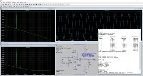
Here's my story: about 30 years ago, I moved to my current apartment, and my stacked Quad 57 had to go; so I though, maybe add a subwoofer and spare the Quad the indignity of dealing with deep bass. So I setup an active xover, nothing fancy, Linkwitz 4th order with 2 Sallen & Key, each built with the cell below, again nothing fancy, but it sims great and physically measures OK, double 0's THD, no NFB:
Wired it up, listened, and was HORRIFIED! The sound lost the liquidity, as if someone chopped off the tail of each note with an axe. Well, maybe it needed breaking in, we'll see. But after a few weeks, I threw in the towel, replaced the whole hi-pass section with a single polystyrene to make a 1st order 80Hz hi-pass. Magic BACK! (at least in the mid & hi)
Post-mortem: the hi-pass section uses 4 polystyrene caps, should be benign, and a MPK output cap, not as good, but I already have many elsewhere in the system. That leaves the follower. What is the explanation? I don't know; as a tube guy, I know I have to avoid followers whenever possible, but driving 20R headphones without one can be hard.
Attachments
Actually I like followers, especially open loop. I use them, instead as IC based followers with some success. I also like to use them for Sallen Key filters as well.
The problem happens when you put a follower in the feedback loop with a gain stage. Then the second (or first stage sometimes) stage develops a lot more gain, because it is buffered from the external load and the Miller feedback REDUCES the open loop bandwidth, while increasing the open loop gain. This is essentially why OPA's have so much open loop gain, and usually limited open loop bandwidth.
I designed the JC-2 type drive stage following Otala's suggestions and have never looked back to op amps, except when necessary, or perhaps more convenient.
Wired it up, listened, and was HORRIFIED! The sound lost the liquidity, as if someone chopped off the tail of each note with an axe.
I'm disappointed I thought you might not need the exaggerations. The Pass Labs folks (like Patrick (EUVL)) have posted extensively on simple source follower circuits I never saw anything like this. I have not had any issue either so in the spirit of everyone's perception has equal weight there is no problem with source followers at all.
Please forgive my innocent question to try to get to a partial conclusion:
Which HPA kit seems to be the best bet at the moment? Who's selling the "best compromise"?
While the E5 was a decent amp, it is no longer available, for about 5 years. The “E19” is actually a copy of the amp, but has some power supply issues, maybe some component issues, is a thread here tending to some of that.
> What is the explanation?
Did you check it with a scope up to say 50MHz ?
What is the value of your gate stopper ?
I use them everywhere.
So nothing wrong with the circuit itself.
Patrick
Did you check it with a scope up to say 50MHz ?
What is the value of your gate stopper ?
I use them everywhere.
So nothing wrong with the circuit itself.
Patrick
Even a 2SK209 without cascode will oscillate in a Sallen Key.
Depends on source impedance.
Patrick
Depends on source impedance.
Patrick
...
Did you check it with a scope up to say 50MHz ?
What is the value of your gate stopper ?
...
The two FET easy cascode is very prone to oscillation at 50+MHz.
That's a sound hypothesis.
At that time, I had a 35 MHz Trio scope; still, it would show something if there're oscillations above that frequency.
The gate stoppers are 1K. And the serie caps are 39nF, so it's a fairly high impedance network.
The xover is still being used as active lo-pass today, but there's a 30 years layer of sediment on top of it. I'll check again with my 100 MHz Tek and report back, but the digging will take a bit.
Last edited:
...
The problem happens when you put a follower in the feedback loop with a gain stage. Then the second (or first stage sometimes) stage develops a lot more gain, because it is buffered from the external load and the Miller feedback REDUCES the open loop bandwidth, while increasing the open loop gain. This is essentially why OPA's have so much open loop gain, and usually limited open loop bandwidth...
Assuming we need a follower, then, as you said, the VAS is a major big deal: it's where most of the gain happens, contrary to a tube power amp where the gain is distributed.
Now what about applying local shunt FB in the VAS?
It lets you dial in the gain you want, within reasons, and it SIMs OK, as in the .ASC I posted earlier.
You need a follower with 30 ohm loads. 300 is marginal, it could go either way. Above 1K, no follower is recommended. Of course you could add internal feedback to reduce the gain to the follower, like I did with the Levinson JC-3 power amp or even throw away the VAS gain, like the original Otala amplifier did, but less is best, all else being equal.
This board (E4)that Zung has started the thread about is actually ten years old I think, the ones that are for sale are all left over from years ago.
The E5 that followed has been sold out and hasn’t been produced for several years either.
A couple years ago I purchased the “E4” to use since the E5 was mia. I recently added an aluminum volume knob, and shortly afterwards had an esd incident (dress shoes/carpet) that took out the input fets I’m assuming.
I saw this thread and decided to buy one of these kits: thought it would be a fun challenge and I might learn something. I appreciate all the great info Zung & others have provided, including the sims and suggested mods.
A little on my experience with the kit so far and then some questions.
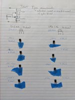
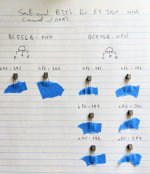
JFETs and BJTs:
I measured the IDSS of the JFETS (haven't measured the Yfs/Gm yet). I didn't control the temperature so take these #'s with a grain of salt.
I also used my DMM's hFE tester to measure the hFE of the small signal transistors.
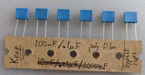
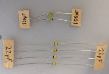
Rather than ceramic bypass caps, my kit came with .1uF poly caps, so I plan to use those. It also came with two types of small axial-leaded caps of a type I've never seen before (pictured) which I assume to be the 22pF and 100pF's based on the schematic and my powers of inference alone. I don't think my DMM can properly measure down the picofarad range.
Misc other parts:
Some of the electrolytics are labeled Nichicon, even some Silmic II's. Plan to use a mixture of what came in the kit and what I have in stock (plenty of electrolytics left over from other projects). I received the same sinterglass ultra-fast diodes for the rectifier.
The heatsinks do indeed seem wimpy -- waiting to receive the case but it's TBD whether or not I will use them versus mounting the MOSFETs to the chassis. Drilling holes in metal is not my favorite activity, even in quarantine.
Questions:
Thanks again for all the great info and in advance for any advice.
A little on my experience with the kit so far and then some questions.
JFETs and BJTs:
I measured the IDSS of the JFETS (haven't measured the Yfs/Gm yet). I didn't control the temperature so take these #'s with a grain of salt.
- 2SJ103: 9.34, 9.45, 9.52, 9.52mA
- 2SK246: 9.71, 9.74, 9.77, 9.79mA
I also used my DMM's hFE tester to measure the hFE of the small signal transistors.
- BC556B: 292, 300
- BC546B: 281, 282, 286, 286, 286, 287
Rather than ceramic bypass caps, my kit came with .1uF poly caps, so I plan to use those. It also came with two types of small axial-leaded caps of a type I've never seen before (pictured) which I assume to be the 22pF and 100pF's based on the schematic and my powers of inference alone. I don't think my DMM can properly measure down the picofarad range.
Misc other parts:
Some of the electrolytics are labeled Nichicon, even some Silmic II's. Plan to use a mixture of what came in the kit and what I have in stock (plenty of electrolytics left over from other projects). I received the same sinterglass ultra-fast diodes for the rectifier.
The heatsinks do indeed seem wimpy -- waiting to receive the case but it's TBD whether or not I will use them versus mounting the MOSFETs to the chassis. Drilling holes in metal is not my favorite activity, even in quarantine.
Questions:
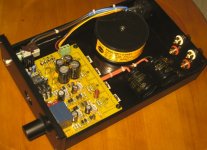
- Rather than doing the PSU mods suggested above, I was planning to install two larger main filter caps (10,000 or 12,000uF) off-board as in the photo and bypass these with .1uF film caps on the board. However, I purchased a transformer with 2x 18V (rather than 15V) secondaries. I see that is how it's set up in the example photo -- any issues running this kit with the stock power supply w/ 18VAC input? (From what I can tell of the ratings on the caps, the 7812, etc. -- should be fine)
- Any particularly urgent reason not to use the supplied BJT's? I have tons of KSA992/KSC1845's lying around but they use a different pinout.
- Rather than deal with the mystery 22pF and 100pF (presumably) caps, I was planning to follow Zung's substitution guide and use 22pF and 100pF Micas in their place. Thoughts/opinions? Holy hell they're expensive.
- I will probably try the IRF710/9610 MOSFETs for the output stage; looking to stick to easily-available parts on Mouser.
Thanks again for all the great info and in advance for any advice.
Attachments
Hey metaphile, thank you for your kind words. I'm in the process of moving to a new place, so everything is boxed, and I can only gives answers from memory. Be aware I'm world famous for the fact that I've got 3.5 neurons left, so feel free to mark my words as suspicious. 🙂
Power supply
2x18V will give you about +/-25Vdc, the semiconductors will take it, so it should work.
Regarding the sound of passive vs active PSU, I did an experiment about 40 years ago: in the blue corner, a SS preamp, based on a pretty standard topology: Fet in, BJT VAS, MOSfet out and on-board cap multipliers; this one has a regulated PSU, all discrete, low loop gain & high bandwidth. In the red corner, the exact same preamp with a passive PSU with 4 massives caps, 100,000uF each I think. The contest was done, sighted and long term, with a grand total of 2 test subjects: me and a friend. The verdict:
Active:
BJT's
No technical reason not to use the supplied ones, especially yours have better Hfe match than mine.
Cap
Compensation: the supplied ones could be ceramic (= evil). Mica's are better alternatives, and polystyrene are best, but they'll need a bit of yoga to fit, maybe vertically.
Bypass: what makes you think the supplied ones are poly's? Anyway, mylar/polyester's are only slightly less evil than ceramics. I use polyprop's, the Chinese ones are only a quarter a piece.
Electrolytics: I wouldn't rely on the markings of the supplied ones. I used them only in the protection circuit, with the exception of BC5, for which I use a Silmic. Everything else are either true blue Silmics or Nichicon UKT's; they're available at Digikey.
Power supply
2x18V will give you about +/-25Vdc, the semiconductors will take it, so it should work.
Regarding the sound of passive vs active PSU, I did an experiment about 40 years ago: in the blue corner, a SS preamp, based on a pretty standard topology: Fet in, BJT VAS, MOSfet out and on-board cap multipliers; this one has a regulated PSU, all discrete, low loop gain & high bandwidth. In the red corner, the exact same preamp with a passive PSU with 4 massives caps, 100,000uF each I think. The contest was done, sighted and long term, with a grand total of 2 test subjects: me and a friend. The verdict:
Active:
- Solid bass
- Slightly subdued mid
- Slightly limited dynamics
- Slightly wooly bass
- Better mid
- Better dynamics
BJT's
No technical reason not to use the supplied ones, especially yours have better Hfe match than mine.
Cap
Compensation: the supplied ones could be ceramic (= evil). Mica's are better alternatives, and polystyrene are best, but they'll need a bit of yoga to fit, maybe vertically.
Bypass: what makes you think the supplied ones are poly's? Anyway, mylar/polyester's are only slightly less evil than ceramics. I use polyprop's, the Chinese ones are only a quarter a piece.
Electrolytics: I wouldn't rely on the markings of the supplied ones. I used them only in the protection circuit, with the exception of BC5, for which I use a Silmic. Everything else are either true blue Silmics or Nichicon UKT's; they're available at Digikey.
These must be small enough ?
100V 500V 5PF~91PF Silver Mica Capacitor Copper Foot Audio Electrical Equipment | eBay
😉
Patrick
100V 500V 5PF~91PF Silver Mica Capacitor Copper Foot Audio Electrical Equipment | eBay
😉
Patrick
- Home
- Amplifiers
- Headphone Systems
- The JC2-HPA Headphone Amplifier