The E19 page at Yuan Jing Audio.
Yuan Jing Audio - E19 Class-A Headphone Amplifier - USD $30.00
You made posts at the 2016 E19 thread that I started. natawa made very helpful mod suggestions. I hope to update the thread with my latest mod to the E19 in the next 2 weeks.
https://www.diyaudio.com/forums/headphone-systems/294456-e19-headphone-amplifier-board-k2381-j407-mosfet-yuanjing-audio.html#post4778402
I do recall your E19 thread.
I have been looking at both the epay ad, and the yuan jing site, but don’t see anything about the input fets however. Am wondering what parts they are using, maybe KSA992 perhaps?
The KSA992 is a BJT, most likely a rebranding of the 2SA992. Japanese naming convention (JIS): A for small signal BJT.
Given the stock situation of the 2SK170 (depleted), I wouldn't be surprised to find 2SK246 instead. It's OK, a bit noisier, and a bit more distortion, you'll live.
Given the stock situation of the 2SK170 (depleted), I wouldn't be surprised to find 2SK246 instead. It's OK, a bit noisier, and a bit more distortion, you'll live.
Oh right, oops. Thanks for correcting that.
Was curious as to what they used, will have to try and dig into mine when it arrives from, of all places, Wuhan...
I have the E5 at home now since work was up in the air there for a while, so maybe I can compare some things.
Was curious as to what they used, will have to try and dig into mine when it arrives from, of all places, Wuhan...
I have the E5 at home now since work was up in the air there for a while, so maybe I can compare some things.
The E19 PCB shows that the input jFET pair to be K170. The 1% matching info must be from their old ad. Nontheless, I take all these e-bay/Chinese seller information with a grain of salt. The ad also said that the output bias is 100mA, but I measured 45mA instead. It is still deep in class A for my Sennheiser HD-600, but I still increase it to 60mA to increase the class A margin. I did not go all the way to 100mA to keep the output MOSFET case below 120°F (the goal is less than 40°F above ambient). It is the MOSFET case surface temperature, not the headphone amp enclosure case.Oh right, oops. Thanks for correcting that.
Was curious as to what they used, will have to try and dig into mine when it arrives from, of all places, Wuhan...
I have the E5 at home now since work was up in the air there for a while, so maybe I can compare some things.
I doubt the K170 are genuine, but the match is good. Over 4 years, the output DC offset stayed in single digit mV and noise is low enough so I did not bother to change them.
Please, review the old E19 thread for necessary mod.
Last edited:
That sounds promising anyways, thanks for the info, and I am not so positive that the E5 has those parts as described either, but it sounds great just the same.
... Over 4 years, the output DC offset stayed in single digit mV and noise is low enough so I did not bother to change them...
Did you short out the feedback capacitor?
It should be a low voltage high capacitance electrolytic near the gate of the second Fet, maybe 50-200uF. 10-20V. It reduces the DC gain to 1 and therefore minimizes the offset/drift. But it's also in the signal path and can be evil.
Last edited:
No. I did not notice that in the signal path or the feedback in the PCB pictures. There are a bunch of low voltage high capacitance electrolytic around the UPC1237 which are not in the signal path.Did you short out the feedback capacitor?
It should be a low voltage high capacitance electrolytic near the gate of the second Fet, maybe 50-200uF. 10-20V. It reduces the DC gain to 1 and therefore minimizes the offset/drift. But it's also in the signal path and can be evil.
I will open the headphone amp box to look again later today.
If it is there to reduce the DC gain to 1, it passes through the input stage DC offset, but should not reduce it.
Last edited:
What I mean is: if you have a mismatch of 1mV at the input, and a DC gain 10, the offset at the output would be 10mV, unless you have a, let's call it "DC feedback blocking cap", in which case the DC gain is 1.
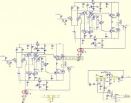
These are the ones I circled in red in the attached schematic.
These are the ones I circled in red in the attached schematic.
Attachments
Just curious Zung, but which schematic would that be?
I agree regarding the DIBUY, but it definitely gives a leg up when have limited amounts of time to perform hobbies.
I agree regarding the DIBUY, but it definitely gives a leg up when have limited amounts of time to perform hobbies.
It's from one of those Ali/eBay headphone amps advertised as Audio-Technica HA5000 clone; should be close to the E5, I think.
Edit: silly me, weiliang published the E5 schematic, and it's a DC amp (no NFB cap):
It's pretty close to the AT, sans the driver.
Edit: silly me, weiliang published the E5 schematic, and it's a DC amp (no NFB cap):
It's pretty close to the AT, sans the driver.
Last edited:
Zung shows the schematic of E5 that Weilliang posted at this forum in 2012. I do not have the E5 and do not know how much detail and fidelity Weilliang showed of the actual board.Ah, ok, wasn’t sure, didn’t recognize it...
On the AT HA-5000 discussion thread, we call this the small blue PCB clone. I bought one of this, but decided to sell it and kept the E19.What I mean is: if you have a mismatch of 1mV at the input, and a DC gain 10, the offset at the output would be 10mV, unless you have a, let's call it "DC feedback blocking cap", in which case the DC gain is 1.
These are the ones I circled in red in the attached schematic.
The other AT HA-5000 clone made by Zero Zone is a 3 PCB kit and a copy of the Shanling PH-100. The Shanling PH-100 is supposed to be a clone of the AT HA-5000. This does not have the 100uF electrolytic in the feedback.
Shanling PH100 | Page 4 | Headphone Reviews and Discussion - Head-Fi.org

It's not going to be "JC2" at all, is it? It's not going to be a PJFET diffpair whose tail is connected to the tail of a NJFET diffpair, and each of the diffpairs drives a voltage-in, current-out common base amplifier using the Lender topology.
Might as well dream up a new name and start up a new thread.
Might as well dream up a new name and start up a new thread.
This little excursion is not without merit though.
Let's do a little recap of the 3 topologies, the basis is PMA's paper linked by EUVL. The DUT is a 2SK389V JFet, we looking at the THD in the drain current, and I skip the finer details, keeping only the baselines:
The complementary differential is done with the addition of 2x 2SJ109V. Note that running the quad at Idss brings the THD down to 0.001%
Personally, I don't need more convincing.
All you need is a way to purchase, measure, and match the unobtanium JFETs that John Curl used in 1974. What could be easier? As we used to say in the old glory days when two-comma grants routinely arrived from an entity called "ARPA" instead of "DARPA",
This is a problem that can be solved by the application of mere money.
This is a problem that can be solved by the application of mere money.
The industry have moved to highly integrated chip and SMD components. The audio DIY crowd remain in the stone age with through hole component which the big semiconductor houses no longer support. The pattern and IP protection of those unobtanium JFETs that John Curl used in 1974 are likely expired. They are NOT difficult for small foundry in Asia to duplicate. But the quality control of this small foundry in Asia are likely to be poor. It is up to the hobbyist to test, sort and match to get what they want. Sharing information on those sources is important to our community too.
I do not kid myself. My resources for hobby is limited. I cannot do what the highend audio lab do. With careful shopping and sharing at this forum, I can still have fun.
I do not kid myself. My resources for hobby is limited. I cannot do what the highend audio lab do. With careful shopping and sharing at this forum, I can still have fun.
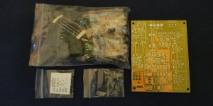
My 2nd kit came in today: ordered on Jan 18th, shipped on Mar 11th, and received on Apr 20th, oh well, nobody's fault I presume...
The content is not as great as the 1st kit: the supplier clearly has some problems with their testing process: the same sex matching is near perfect, the opposite sex matching is terrible. I left the following feedback:
Good item, great value, but...
The matching of the input FET needs improvement:
- All the N-channels are well matched: 8.89, 8.89, 8.88, 8.89; average is 8.89 mA: excellent
- All the P-channels are well matched 11.73, 11.71, 11.76, 11.73; average is 11.73 mA: excellent
***BUT the matching between N and P is BAD!!!***
Clearly, this is a problem with the testing process. Please forward this mail to your supplier so they can fix it.
Attachments
Last edited:
It seems to confirm that, in Chinese kit, a differential input is easier to implement than the complementary differential input.
The K170 and J74 are relative cheap from Chinese sellers on e-bay. Did anyone see any test report on them? How easy is it to find a matched quad?
I used to have a Harmon Kardon AP2500 preamp. It uses a complementary differential input for the MC phono stage. I found it to be excellent and even better than the older HK Citation 21 preamp's differential phono stage. I have only one data set. I do believe a complementary differential input with matched quad is better than a differential input on paper and audible in MC phono stage. Does it have same effect on headphone amp? I am very interested in knowing.
Last edited:
- Home
- Amplifiers
- Headphone Systems
- The JC2-HPA Headphone Amplifier